
Page 13 - Parker - Rodless Air Cylinders
P. 13
Catalog #AU03-0928/NA Sizing Guidelines
Application Notes Rodless Cylinders
Intermediate Stroke Stop – Band-Type Cylinders
Band-type rodless cylinders, by the nature of their an intermediate position, more satisfactory results will
design, will allow a very small amount of air to leak be achieved using a three position valve with both
externally including the P1X and P1Y which have cylinder ports open to pressure in the center position. A
minimal leakage. To try to stop and hold a cylinder in See Figures 2 and 3 for more information.
Horizontal Load Vertical Load
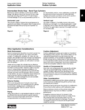
The circuit in Figure 2 shows that equal pressure is As shown in Figure 3, the table moves in the same
applied to both sides of the piston when it stops which direction as the weight in a vertical application. Install
prevents the table from jumping out of position at a regulator with a check valve to reduce the cylinder
restart. thrust on the upper side to balance the weight and force
on the lower side.
Figure 2 Figure 3
Other Application Considerations
Work Environment Cushion Adjustment
System components should be mounted in areas free Cushion adjustment screws are located on the side of
from corrosive atmosphere, rain, water and direct the endcaps of the cylinder. The cushion effect can be
sunlight. If cutting oils, coolants, oil mists, etc. are reduced by loosening the cushion screw (turning
present, the cylinder should be covered or protected to counterclockwise). If the cylinder is subjected to high
avoid damage to the seals. Also, avoid areas where kinetic energy due to a heavy load or high speed, etc.,
cutting chips, dust, spatter, etc. will come in contact an external deceleration device should be considered to
with the cylinder. absorb the kinetic energy load. See stroke adjustment
and shock absorption option for more information.
Under normal usage, the cylinder has an effective
outer seal which prevents contamination from entering Quality of Compressed Air
the interior of the cylinder. However, under unusually Use clean, dry compressed air to operate the cylinder.
dusty or contaminated operating conditions, it is This can be accomplished by installing a filter with
recommended that the cylinder be mounted with the a proper filtration rating and flow rate ahead of the
carriage and outer seal facing down. When mounted directional control valve and draining the filter regularly
in this fashion, be sure to check the weight deflection to ensure that no moisture or contaminants are allowed
chart to ensure that the unsupported tube is not into the system.
overloaded. Inverted carriage mounts are available
for use in these circumstances. Other Considerations
Avoid electric welding around the rodless cylinder as
External Guides
current could be conducted through the cylinder tube
When external guides are employed, ensure that and destroy the cylinder.
excessive forces are not transmitted to the cylinder
due to friction, misalignment, or deflection of Excessive inertia will cause the cylinder to malfunction.
the external guides. Use of a swivel mount is Ensure that inertial loads are within allowable range.
recommended. Deep scratches or dents on the cylinder tube from
external means may have an effect on cylinder
Piping performance.
Piping should be of a rust resistant material and be of
a sufficient internal area for piston speed required. If negative pressure (vacuum) is caused in the
Make sure that piping is clean and free from sealing cylinder by excessive external force or inertial force,
compound before connecting to system. the pressure seal may be drawn away from the
cylinder body causing external leakage. Ensure that
no negative pressure or vacuum can be generated
inside the cylinder.
Parker Hannifin Corporation
5 Actuator Division
Wadsworth, OH 44281