
Page 15 - Parker - Rodless Air Cylinders
P. 15
Catalog #AU03-0928/NA Sizing Guidelines
Sizing Forms Rodless Cylinders
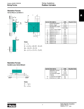
Resistive Forces
Vertical Mount, Condition 3
z z
Yf A
Xf
XL Fz Fz
Fx Fy Symbol Description Units Required Data
Zf Operating Pressure PSI
x x y y
Stroke Length Inches
ZL
Unsupported Length Inches
Velocity Inches/Sec
L Load & Fixture Weight Lbs.
Fx Resistive Force - X Lbs.
Fy Resistive Force - Y Lbs.
L Fz Resistive Force - Z Lbs.
L
XL Distance XL Inches
z YL Xf Distance Xf Inches
Fy z
YL Distance YL Inches
Fx
Yf Distance Yf Inches
Notes: ZL Distance ZL Inches
Zf Distance Zf Inches
LT =Fx
y M= (L XL) + (Fz Xf) - (Fx Zf)
*
*
*
Ms = (Fy Xf) - (Fx Yf)
*
*
x x
Mv = (L YL) + (Fz Yf) - (Fy Zf)
*
*
*
y
Resistive Forces
Guided Load, Swivel Mount
z
Symbol Description Units Required Data
Operating Pressure PSI
Stroke Length Inches
Unsupported Length Inches
Fg
s
Velocity Inches/Sec
x x Lg Load & Fixture Weight Lbs.
µ Coefficient of Friction N/A
z
Notes:
M= Fg s
*
Fg = µ Lg
*
Parker Hannifin Corporation
7 Actuator Division
Wadsworth, OH 44281