
Page 18 - Parker - Rodless Air Cylinders
P. 18
Catalog #AU03-0928/NA Sizing Guidelines
Technical Data Rodless Cylinders
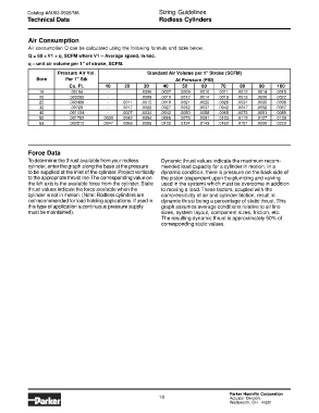
Air Consumption
Air consumption Q can be calculated using the following formula and table below.
Q = 60 V1 q, SCFM where V1 – Average speed, in/sec.
* *
q – unit air volume per 1" of stroke, SCFM.
Pressure Air Vol. Standard Air Volume per 1" Stroke (SCFM)
Bore Per 1" Stk At Pressure (PSI)
Cu. Ft. 10 20 30 40 50 60 70 80 90 100
16 .00194 - - .0006 .0007 .0009 .0010 .0011 .0012 .0014 .0015
20 .000282 - - .0009 .0010 .0012 .0014 .0016 .0018 .0020 .0022
25 .000486 - .0011 .0015 .0018 .0021 .0025 .0028 .0031 .0035 .0038
32 .00729 - .0017 .0022 .0027 .0032 .0037 .0042 .0047 .0052 .0057
40 .001134 - .0027 .0034 .0042 .0050 .0058 .0065 .0073 .0081 .0088
50 .001782 .0030 .0042 .0054 .0066 .0078 .0091 .0103 .0115 .0127 .0139
63 .002812 .0047 .0066 .0086 .0105 .0124 .0143 .0162 .0181 .0200 .0220
Force Data
To determine the thrust available from your rodless Dynamic thrust values indicate the maximum recom-
cylinder, enter the graph along the base at the pressure mended load capacity for a cylinder in motion. In a
to be supplied at the inlet of the cylinder. Project vertically dynamic condition, there is pressure on the back side of
to the appropriate thrust line. The corresponding value on the piston (dependent upon the plumbing and valving
the left axis is the available force from the cylinder. Static used in the system) which must be overcome in addition
thrust values indicate the force available when the to moving a load. These factors, coupled with the
cylinder is not in motion. (Note: Rodless cylinders are compressibility of air and cylinder friction, result in
not recommended for load holding applications. If used in dynamic thrust being a percentage of static thrust. This
this type of application a continuous pressure supply graph assumes average conditions relative to air line
must be maintained). sizes, system layout, component sizes, friction, etc.
The resulting dynamic thrust is approximately 50% of
corresponding static values.
Parker Hannifin Corporation
10 Actuator Division
Wadsworth, OH 44281