
Page 97 - Parker - Rodless Air Cylinders
P. 97
Sensors
Catalog #AU03-0928/NA Sensors
Drop-In Sensors
Reed Sensor Specifications Drop-In Sensors
Drop-In Reed Sensor Part Numbers
REED Wiring
P8S-GRFLX 3m flying leads
P8S-GRFTX 10m flying leads
P8S-GRSHX .2m lead with 8mm connector
P8S-GRMHX .2m lead with 12mm connector
P8S-GRSCX 1m lead with 8mm connector
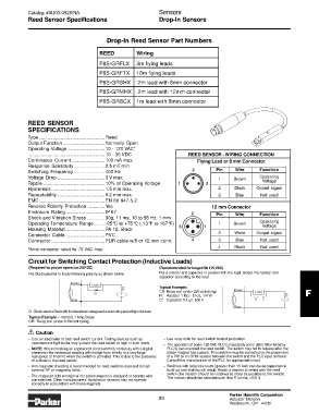
REED SENSOR
SPECIFICATIONS
Type ..................................................Reed
Output Function ................................Normally Open
Operating Voltage ............................10 - 120 VAC*
..........................................................10 - 30 VDC REED SENSOR - WIRING CONNECTION
Continuous Current .........................100 mA max. Flying Lead or 8 mm Connector
Response Sensitivity .......................2.5 mT min.
Switching Frequency........................400 Hz 2 Pin Wire Function
Voltage Drop ....................................3 V max. 1 Brown Operating
Ripple ...............................................10% of Operating Voltage 1 3 Voltage
Hysteresis .........................................1.5 mm max. 2 Black Output signal
Repeatability ....................................0.2 mm max. 3 Blue Not used
EMC ..................................................EN 60 947-5-2
Reverse Polarity Protection .............Yes 12 mm Connector
Enclosure Rating..............................IP 67 2 Pin Wire Function
Shock and Vibration Stress ..............30g, 11 ms, 10 to 55 Hz, 1 mm
Operating
Operating Temperature Range ........-25°C to +75°C (-13°F to 167°F) 3 1 1 Brown Voltage
Housing Material ..............................PA 12, Black
Connector Cable ..............................PVC 2 White Output signal
Connector .........................................PUR cable w/8 or 12 mm conn. 4 3 Blue Not used
4 Black Not used
*8mm connector rated for 75 VAC max.
Circuit for Switching Contact Protection (Inductive Loads)
(Required for proper operation 24V DC) (Recommended for longer life 125 VAC)
Put Diode parallel to loads following polarity as shown below. Put a resistor and capacitor in parallel with the load. Select the resistor and
capacitor according to the load.
Brown
Load
Typical Example:
CR: Relay coil (under 2W coil rating) Brown Load
DC
D F
R: Resistor 1 KΩ - 5 KΩ, 1/4 W AC
Blue C: Capacitor 0.1 µF, 600 V R C
Blue
D: Diode: select a Diode with the breakdown voltage and current rating according to the load.
Typical Example—100 Volt, 1 Amp Diode
CR: Relay coil (under 0.5W coil rating)
Caution
!
– Use an ampmeter to test reed switch current. Testing devices such as – Use relay coils for reed switch contact protection.
incandescent light bulbs may subject the reed switch to high in-rush loads.
– The operation of some 120 VAC PLC’s (especially some older Allen-Bradley
– NOTE: When checking an unpowered reed switch for continuity with a digital PLC’s) can overload the reed switch. The switch may fail to release after the
ohmmeter the resistance reading will change from infinity to a very large piston magnet has passed. This problem may be corrected by the placement
resistance (2 M ohm) when the switch is activated. This is due to the presence of a 700 to 1K OHM resistor between the switch and the PLC input terminal.
of a diode in the reed switch. Consult the manufacturer of the PLC for appropriate circuit.
– Anti-magnetic shielding is recommended for reed switches exposed to high – Switches with long wire leads (greater than 15 feet) can cause capacitance
external RF or magnetic fields. build-up and sticking will result. Attach a resistor in series with the reed
switch (the resistor should be installed as close as possible to the switch).
– The magnetic field strength of the piston magnet is designed to operate with The resistor should be selected such that R (ohms) >E/0.3.
our switches. Other manufacturers’ switches or sensors may not operate
correctly in conjunction with these magnets.
Parker Hannifin Corporation
89 Actuator Division
Wadsworth, OH 44281