
Page 179 - Parker - Republic/Manatrol (Hydraulic and Pneumatic Control Valves)
P. 179
Catalog HY14-3000/US Pressure Control Valves
Performance Curves Series 620 - 649
Factory Pressure Dash Range Factory Pressure
Setting PSI Flow Capacity No. PSI Setting PSI Flow Capacity
3200 3100 3200
2600 3000 12 to 2600 3000
2800 2000 2800
2800 2750 2800
2200 2600 11 to 2200 2600
2400 1500 2400
2200 2100 2200
1750 2050 10 to 1750 2050
1900 1400 1900
1300 1500 1300
1000 1200 9 to 1000 1200
1100 800 1100
1000 1020 1000
850 950 8 to 850 950
900 630 900
825 850 825
750 800 7 to 750 800
775 630 775
640 650 640
550 610 6 to 550 610
580 430 580
420 450 420
360 400 5 to 360 400
380 235 380
230 250 230
200 220 4 to 200 220
210 115 210
120 125 120
90 110 3 to 90 110
100 40 100
50 2 50 35 50
to
45
35
E 40 10 40
45
22
15
22
10 18 1 to 10 18
40 4 40
1 2 3 5 10 20 50 100 200 500 0 2 4 6 8 10 12 14 16 18 20
1/2", 3/4"
Rate of Flow SCFM 1/8", 1/4", 3/8" Rate of Flow GPM
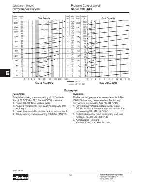
Examples
Pneumatic: Hydraulic:
Establish cracking pressure setting of 1/2" valve for Find amount of pressure increase above 24.8 Bar
flow of 70 SCFM at 27.6 Bar (400 PSI) pressure: (360 PSI) cracking pressure when flow through
1. Project 70 SCFM on vertical scale. 3/4" valve is increased to 54 LPM (14 GPM):
2. Project 27.6 Bar (400 PSI) scale horizontally inter- 1. From 360 on vertical pressure scale, follow
sectiong 1. 3/4" curve until it intersects with the vertical line
3. Project line parallel to curves back to vertical line 1. representing 54 LPM (14 GPM).
4. Read cracking pressure setting: 24.8 Bar (360 PSI). 2. Project intersecting point horizontally and read
pressure, i.e., 29 Bar (420 PSI).
3. Accumulated Pressure:
420 minus 360 = 4.1 Bar (60 PSI).
3000-E1.p65, dd
E4 Parker Hannifin Corporation
Hydraulic Valve Division
Elyria, Ohio, USA