
Page 46 - Parker - Hydraulic Motor/Pump
P. 46
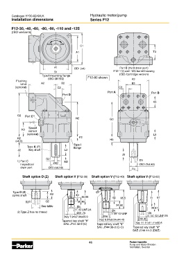
Catalogue HY30-8249/UK                             Hydraulic motor/pump
        Installation dimensions                            Series F12

        F12-30, -40, -60,  -80, -90, -110 and -125
        (ISO versions)


                               ccw      cw
                                                    C1
                                                  A1                                               T3


                                    A1           ØD1 (x4)                     Port E (third drain port)
                                    B1                                    F12-110 and -125 barrel housing
                            Type I mounting flange                           (ISO /cartridge version)
                                (ISO 3019/2)             F12-80 shown                A3
           Flushing
              valve        A2           B2                                           B3
           (optional)                 C2                                     C3
                                                                      Port A                      Port B
                                         Port D

                                                                                                   K3


            G2   Port C 1)
                                                  N2                   G3

                   Speed
               K2  sensor
                  (optional)                                                                       L3
            H2                                      P2
           (±0,5)                                                      H3
                                                Type I
                  Type K (P)                    flange
            J2     Key shaft              L2
                                                                               J3
                               D2
            1)  Port C                    M2                                              D3
              Inspection/          ØE2                                                    ØE3 (Tol. k6)
              drain port        ØF2 (tol. h8)
                                                                                     F3

               Shaft option D (Z)   Shaft option V (F12-30)  Shaft option V (F12-40) Shaft option V (F12-60)


         Type D (Z)                                            R2
         spline shaft            R2               49
                                                     65.88               62   85.5               71  97
                 S2 2)        Q2                   30.96
                           See table              Ø4                       34.92                  39.67
                                                 1˝-12 UNF-2A            Ø4
            2) Type Z has no thread               Ø31.75                1 1/8˝-12 UNF           Ø4
                                          Key 7.94x7.94x25.9       Ø38.1                        1 1/4˝-12 UNF-2A
                                         Tapered key shaft "V"   Key 9.54x9.54x44.45     Ø44.45
                                          SAE J744 32-3 (C)    Tapered key shaft "V"    Key 11.11x11.11x50.8
                                                               SAE J744 38-3 (C-C)    Tapered key shaft "V"
                                                                                      SAE J744 44-3 (D&E)


                                                          46                        Parker Hannifin
                                                                                    Pump and Motor Division
                                                                                    Trollhättan, Sweden