
Page 5 - Parker - Hydraulic Motor/Pump
P. 5
Catalogue HY30-8249/UK Hydraulic motor/pump
Technical information Series F11/F12
Bearing life
General information Required information 1
Bearing life can be calculated for that part of the load/ When requesting a bearing life calculation from Parker
life curve (shown below) that is designated 'Bearing Hannifin, the following information (where applicable)
fatigue'. 'Rotating group fatigue and wear' and 'Other' should be provided:
caused by material fatigue, fluid contamination, etc. - A short presentation of the application
should also be taken into consideration when estimating
the service life of a motor/pump in a specific application. - F11 or F12 size and version
Bearing life calculations are mainly used when compar- - Duty cycle (pressure and speed versus time
ing different frame sizes. Bearing life, designated B (or at given displacements)
10
L ), is dependent of system pressure, operating speed, - Low system pressure
10
external shaft loads, fluid viscosity in the case, and fluid - Case fluid viscosity
contamination level. - Life probability (B , B , etc.)
20
10
The B value means that 90% of the bearings survive, - Operating mode (pump or motor)
10
at a minimum, the number of hours calculated. Statisti-
cally, 50% of the bearings will survive at least five times - Direction of rotation (L or R)
the B life. - External shaft loads (Forces, Gear, Belt, Cardan
10
or none)
For forces please provide:
- Axial load, Fixed radial load, Bending moment, Ro-
tating radial load and distance flange to radial load.
For Gear please provide:
Life expectancy - Pitch diameter, Pressure angle, Spiral angle, Dis-
(logarithmic scale) tance flange – gearwheel (mid) and Gearwheel
Other spiral direction (R or L).
causes For Belt please provide:
- Pretension, Coefficient of friction, Angle of contact,
Distance flange – pulley (mid) and Diameter pulley.
Bearing For Cardan please provide:
fatigue
- Shaft angle, Distance flange – first joint and dis-
tance between joints
- Angle of attack (α) as defined below
Rotating group
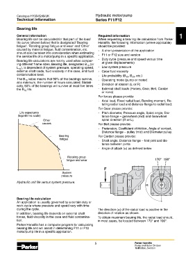
fatigue and wear 170° 190°
F
System
pressure
Bearing_life_DE.eps
Hydraulic unit life versus system pressure.
Leif A./020201 α
Bearing life calculation
An application is usually governed by a certain duty or
work cycle where pressure and speed vary with time
F12_shaft_loads.EPS
during the cycle. The direction (α) of the radial load is positive in the
Leif A./020204
In addition, bearing life depends on external shaft direction of rotation as shown.
forces, fluid viscosity in the case and fluid contamina- To obtain maximum bearing life, the radial load should,
tion. in most cases, be located between 170° and 190°.
Parker Hannifin has a computer program for calculating
bearing life and will assist in determining F11 or F12
motor/pump life in a specific application.
5 Parker Hannifin
Pump and Motor Division
Trollhättan, Sweden