
Page 6 - Parker - Hydraulic Motor/Pump
P. 6
Catalogue HY30-8249/UK Hydraulic motor/pump
Technical information Series F11/F12
F11/F12 Fan motors
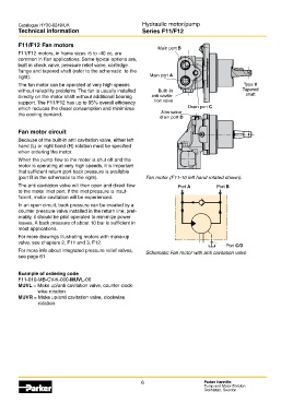
Main port B
F11/F12 motors, in frame sizes -5 to -40 cc, are
common in Fan applications. Some typical options are,
built in check valve, pressure relief valve, cartridge
flange and tapered shaft (refer to the schematic to the
right). Main port A
The fan motor can be operated at very high speeds Type V
without reliability problems. The fan is usually installed Built -in Tapered
directly on the motor shaft without additional bearing anti cavita- shaft
support. The F11/F12 has up to 95% overall efficiency tion valve
which reduces the diesel consumption and minimizes Drain port C
the cooling demand. Alternative
drain port D
Fan motor circuit
Because of the built-in anti cavitation valve, either left
hand (L) or right hand (R) rotation must be specified
when ordering the motor.
When the pump flow to the motor is shut off and the
motor is operating at very high speeds, it is important
that sufficient return port back pressure is available
(port B in the schematic to the right). Fan motor (F11-10 left hand rotated shown).
The anti cavitation valve will then open and direct flow Port A Port B
to the motor inlet port. If the inlet pressure is insuf-
ficient, motor cavitation will be experienced.
In an open circuit, back pressure can be created by a
counter pressure valve installed in the return line; pref-
erably, it should be pilot operated to minimize power
losses. A back pressure of about 10 bar is sufficient in
most applications.
For more drawings illustrating motors with make-up
valve, see chapters 2, F11 and 3, F12.
Port C/D
For more info about integrated pressure relief valves, Schematic Fan motor with anti cavitation valve
see page 61 Fan_motor_schem.eps
Leif A./020204
Example of ordering code
F11-010-MB-CV-K-000-MUVL-00
MUVL = Make up/anti cavitation valve, counter clock-
wise rotation
MUVR = Make up/anti cavitation valve, clockwise
rotation
6 Parker Hannifin
Pump and Motor Division
Trollhättan, Sweden