
Page 59 - Parker - Hydraulic Motor/Pump
P. 59
Catalogue HY30-8249/UK Hydraulic motor/pump
Flushing valves for F12 motors Series F11/F12
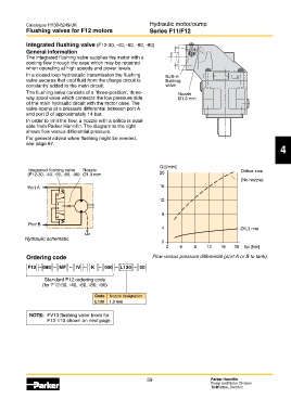
Integrated flushing valve (F12-30, -40, -60, -80, -90)
General information
The integrated flushing valve supplies the motor with a
cooling flow through the case which may be required
when operating at high speeds and power levels.
In a closed loop hydrostatic transmission the flushing Built-in
valve secures that cool fluid from the charge circuit is flushing
constantly added to the main circuit. valve
The flushing valve consists of a ’three-position’, three- Nozzle
way spool valve which connects the low pressure side Ø1.3 mm
of the main hydraulic circuit with the motor case. The
valve opens at a pressure differential between port A
and port B of approximately 14 bar.
In order to limit the flow, a nozzle with a orifice is avail-
able from Parker Hannifin. The diagram to the right
shows flow versus differential pressure.
For general advise when flushing might be needed,
see page 67. F12_60_FV_install.eps
Leif A./03-01-27 4
Q [l/min]
Integrated flushing valve Nozzle Orifice size
(F12-30, -40, -60, -80, -90) Ø1.3 mm 20
(No nozzle)
Port A 16
12
8
Port B
4 Ø1,3 mm
Hydraulic schematic.
F12_FV_schem.eps 0
Leif A./03-01-27 0 4 8 12 16 20 Δp [bar]
Ordering code Flow versus pressure differential (port A or B to tank).
F12 – 080 – MF – IV – K – 000 – L130 – 00
Standard F12 ordering code
(for F12-30, -40, -60, -80, -90)
Code Nozzle designation
L130 1.3 mm
NOTE: FV13 flushing valve block for
F12-110 shown on next page.
59 Parker Hannifin
Pump and Motor Division
Trollhättan, Sweden