
Page 7 - Joyce - Options, accessories and controls
P. 7
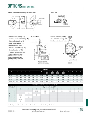
OpTiONS LimiT SwiTChES


            Rotation positions shown looking into end of shaft.         Shaft Detail


            • Machine Screw Jacks (p. 18)   Left Side Mounting         • Bevel Gear Jacks (p. 148)
            • Machine screw ComDRIVEs  (p. 45)                         • Bevel Ball Actuators (p. 159)
                                   ®
            • Stainless Steel Jacks (p. 58)                            Bg and BB are available with all switch positions.
            • Metric Screw Jacks (p. 71)
            • Ball Screw Jacks (p. 80)
            • BallScrew ComDRIVEs (p. 102)
            • Electric Cylinders (p. 118)
            • Integrated Actuators (p. 135)
            2, 3, 5, 10, 15 and 20-ton jacks are available
            with limit switch positions #1, #3 and #5.
            25, 30, 35, 50 and 75-ton jacks are available
            with limit switch positions #1, #4, #7 and #8.
            *Refer to specific product drawing
                                                      Right Side Mounting
                                                      (Rotation PoS #1 Shown)


                                                             Dimensions
                Type     A    B     C    D     E    F     G       H      H       H       H      J     K    M     N
                                                                 BG150   BG250   BG375   BG450
                                                                 BB150  BB225  BB300   BB400
             LS7 402    3.81  6.13  1.75  5.44  5.00  5.63  1/2 NpT  7.63  9.00  10.13  15.22  7.0   3.28  3.88  2.63
             LS8 402    5.50  6.62  2.00  6.75  5.25  6.25  3/4 NpT  7.88  9.25  10.38  15.47  7.62  3.53  5.25  2.46
             LS8 404    6.50  8.38  2.00  8.50  6.25  8.25  1 NpT  8.62  10.00  11.19   16.47  9.62  4.53  5.25  2.46
             LS9 502 — 507  6.31  9.25  1.50  8.69  7.25  8.81  1/2 N pT  9.31  10.75  11.88  16.78  10.19  4.84  5.50  3.31

                                              LS8 (400 Series) and LS9 (500 Series) Switch Combination Chart
              Switch Quantity                                Single-Pole Double-Throw (SPDT)
                             0           1          2          3           4           5          6           7
                     0                            402/502      503       404/504      505         506         507

              D.     1                  402                    404
              p.     2     402/502                 404
              D.     3       503        404
              T.     4     404/504
                     5       505

            Note: Drawings are artist’s conception — not for certification; dimensions are subject to change without notice.


                                Custom products are available • Contact Joyce/Dayton with your requirements   175
            800-523-5204                      sales@joycedayton.com                  joycedayton.com