Page 3 - Destaco - RGD/RGS Series
P. 3

RGD/RGS Series


      Precision Indexing | How To Order


           Indexer Ordering Procedure                           Reducer Ordering Procedure
           1. Model                                             1. Model
           2. Input Shaft Configuration                         2. Ratio
             • Side 1                                             • 10:1, 15:1, 20:1, 25:1, 30:1, 40:1, 50:1, 60:1
             • Side 2                                           3. Motor Adapter
             • Double Input – DI (Standard)
                                                                4. Reducer Input Shaft Extension
           3. Cam Lead (Helix)                                    • Single Input (SE) or Double Input (DE)
             • Right Hand (Standard)
             • Left Hand                                        5. Mounting
           NOTE: Input may rotate in either direction to          • Mounting Position A, B, C, or D
           achieve desired direction of output rotation.          • Mounted on Indexer Side 1 or Side 2
           4. Indexer Mounting Position: 1-6                    6. Input Shaft Orientation
                             Position of Shafts
                                                                             Indexer Mounting Position
           5. Indexer Housing Mounting Holes: Side 1-6 (more      • Left or Right  (See Diagram Below)
             than one side can be selected)                     1                        2
                                                                              AS
                                                                                           AE
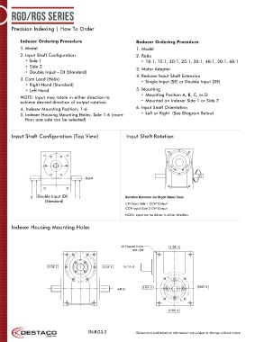
      Input Shaft Configuration (Top View)                  Input Shaft Rotation
                  Position of Shafts            Input                        Indexer Mounting Position
                                                                                AE
                                                                                                     AS
                                                              1  3                       4   2
                           2  Double Input (DI)  1                             AS           AE
                                                                                 AS
                                 (Standard)
                                                                                               AE
                                                                                       CCW                AS
                                Cam Lead
                                                                                CW
                                                                                AE
                                         Input
                                                                                 AE
                    Right Hand                 Left Hand                                                    AS
                                                                5                        6
                                                                        AS
                                                              3                              4
               2  Double Input (DI)   1                    Relative Rotation for Right Hand Cam:  AE
                                                                                  AS
                      (Standard)
                                                           CW Input Side 1 CCW Output                       AS
                                                           CCW Input Side 2 CW Output                            AS
                     Cam Lead                                                AE                  AE
                                                           NOTE: Input can be driven in either direction
                                                                       AE: Input Shaft AE     AS: Output Shaft
      Indexer Housing Mounting Holes
       Right Hand                       Left Hand
                                                              5
                                                Inde xerHou s ing Moun ting Holes            6
                                                                       AS
                                                         (4) Tapped holes       SIDE  4
                                                               per side
                                                                                                                    AS

                       SIDE  2                   SIDE  1  OUTP UT             AE                       AE

                                                                      AE: Input Shaft              AS: Output Shaft

                                                                   SIDE  5                   SIDE  6
                                                       INPUT
                                         Inde xerHou s ing Moun ting Holes


                                                    (4) Tapped holes            SIDE  3  4
                                                                                 SIDE
                                                           per side


                                          IN-RGS-3              Dimensions and technical information are subject to change without notice
          SIDE  2                         SIDE  1     OUTP UT


                                                                 SIDE  5                         SIDE  6
                                                   INPUT


                                                                                 SIDE  3
   1   2   3   4   5   6   7   8