
Page 57 - Exlar - TRITEX 2 series fully integrated servo drive/motor/actuator
P. 57
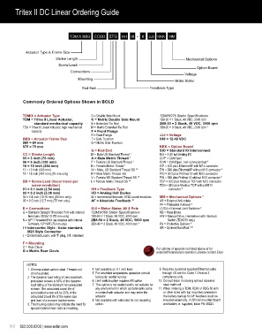
Tritex II DC Linear Ordering Guide

                             Sample Product Number: TDM075-1004-NCW-IE-2B8-30-048-CON-SD-XL


                                 TDM/X BBB   CCDD   EFG   HH  III  - II  JJJ KKK  MM


             Actuator Type & Frame Size
                           Stroke Length                                                Mechanical Options
                            Screw Lead
                                                                                             Option Board
                                  Connections
                                                                                       Voltage
                                      Mounting                                     Motor Stator

                                       Rod End                         Feedback Type


            Commonly Ordered Options Shown in BOLD


            TDM/X = Actuator Type           D = Double Side Mount           TDM/X075 Stator Specifications
            TDM =  Tritex II Linear Actuator,   K = Metric Double Side Mount  1B8-30 = 1 Stack, 48 VDC, 3000 rpm
                 standard mechanical capacity  E = Extended Tie Rod         2B8-30 = 2 Stack, 48 VDC, 3000 rpm
            TDX =  Tritex II Linear Actuator, high mechanical   M = Metric Extended Tie Rod  3B8-20 = 3 Stack, 48 VDC, 2000 rpm  4
                capacity                    F = Front Flange
                                            R = Rear Flange                 JJJ = Voltage
            BBB = Actuator Frame Size       T = Side Trunnion               048 = 12-48 VDC
            060 = 60 mm                     Q = Metric Side Trunnion
            075 = 75 mm                                                     KKK = Option Board
                                            G = Rod End                     SIO = Standard IO Interconnect
            CC = Stroke Length              M = Male US Standard Thread    1  IA4 = 4-20 mA Analog I/O
            03 = 3 inch (76 mm)             A = Male Metric Thread  1       COP =  CANOpen
            06 = 6 inch (150 mm)            F = Female US Standard Thread  1  CON =  CANOpen, non-connectorized  9
            10 = 10 inch (254 mm)           B = Female Metric Thread  1     EIP =  SIO plus Ethernet/IP with M12 connector
            12 = 12 inch (305 mm)           W = Male, US Standard Thread SS  10  EIN =  SIO plus Ethernet/IP without M12 connector  9
            18 = 18 inch (457 mm) (75 mm only)  R = Male Metric Thread  SS  PIO =  SIO plus Profinet IO with M12 connector
                                            V = Female US Standard Thread SS  10  PIN =  SIO plus Profinet IO without M12 connector  9
            DD =  Screw Lead (linear travel per   L = Female Metric Thread SS  10  TCP =  SIO plus Modbus TCP with M12 connector
                screw revolution)                                           TCN =  SIO plus Modbus TCP without M12
            01 = 0.1 inch (2.54 mm)         HH = Feedback Type                  connector  9
            02 = 0.2 inch (5.08 mm)         HD = Analog Hall Device
            04 = 0.4 inch (10.16 mm) (60 mm only)  IE =  Incremental Encoder, 8192 count resolution  MM = Mechanical Options  5
            05 = 0.5 inch (12.7 mm) (75 mm only)  AF = Absolute Feedback  11  AR = External Anti-rotate
                                                                            PF = Preloaded Follower  2
            E = Connections                 III-II = Motor Stator, All 8 Pole   L1/2/3 = External Limit Switches  6
            G =  Standard Straight Threaded Port with internal   TDM/X060 Stator Specifications  RB =  Rear Brake
              terminals, M20x1.5 (75 mm only)  1B8-50 = 1 Stack, 48 VDC, 5000 rpm  HW =  Manual Drive, Handwheel with Interlock
            N =  NPT Threaded Port via Adapter with Internal   2B8-50 = 2 Stack, 48 VDC, 5000 rpm  Switch (TDX075 only)
              Terminals, 1/2” NPT (75 mm only)  3B8-40 = 3 Stack, 48 VDC. 4000 rpm  4  PB = Protective Bellows  8
            I =  Intercontec Style - Exlar standard,                        SR = Splined Main Rod  7,10
              M23 Style Connector
            J =  Embedded Leads, with “I” plug, 3 ft. standard

            F = Mounting
            C = Rear Clevis                                               For options or specials not listed above or for
            G = Metric Rear Clevis                                        extended temperature operation, please contact Exlar


              NOTES:
               1.  Chrome-plated carbon steel. Threads not    4.  Not available on 0.1 inch lead.   9.  Requires customer supplied Ethernet cable
               chrome-plated.                5.   For extended temperature operation consult   through I/O port for Class 1 Division 2
               2.   The dynamic load rating of zero backlash,   factory for model number.  compliance only.
               preloaded screws is 63% of the dynamic    6.  Limit switch option requires AR option.  10.  Consult Exlar if ordering splined stainless
               load rating of the standard non-preloaded    7.   This option is not sealed and is not suitable for   steel main rod.
               screws. The calculated travel life of   any environment in which contaminants come   11. When ordering a TDM, RDM or RDG 60 mm
               a preloaded screw will be 25% of the   in contact with actuator and may enter the      or other sizes with top mounted connectors
               calculated travel life of the same size   actuator.            the battery backup for AF feedback must be
               and lead of a non-pre loaded screw.   8.  Not available with extended tie rod mounting      mounted externally.  A DIN rail mounted board
               3.  This housing option may indicate the need for   option.     and battery is  supplied, Exlar PN 48224.
               special material main rods or mounting.


     112     952.500.6200 | www.exlar.com