
Page 31 - Linde - VT1 Modular, modular system for LSC manifold valve plates
P. 31
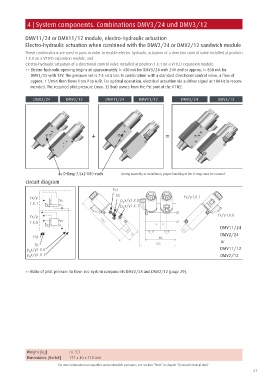
4 | System components. Combinations DMV3/24 und DMV3/12


            DMV11/24 or DMV11/12 module, electro-hydraulic actuation
            Electro-hydraulic actuation when combined with the DMV2/24 or DMV2/12 sandwich module
            These combinations are used in pairs in order to enable electro-hydraulic actuation of a direction control valve installed at position
            1.X.0 on a VT1ED expansion module, and
            electro-hydraulic actuation of a directional control valve installed at position 1.X.1 on a VT1ED expansion module.
            >> Electro-hydraulic opening begins at approximately l= 430 mA for DMV3/24 with 24V and at approx. I= 830 mA for
               DMV3/12 with 12V. The pressure set is 7.5 ±0.5 bar. In combination with a standard directional control valve, a flow of
               approx. 1 l/min then flows from P to A/B. For optimal operation, electrical actuation via a dither signal at 100 Hz is recom-
               mended. The required pilot pressure (max. 32 bar) comes from the Pst port of the VT1EE.


                DMV2/24       DMV2/12           DMV11/24       DMV11/12           DMV3/24         DMV3/12


                                          +                               =


                           4x O-Ring-7,5x2-V80 each    During assembly or installation, proper handling of the O-rings must be ensured.
            circuit diagram

                                                   Pst
              Yx/y                                  T0  p x/y1.X.0                 Yx/y1.X.1
              1.X.1                                    St
                                                       p x/y1.X.1
                                                       St
              Yx/y                                                                                Yx/y1.X.0
              1.X.0
                                                                                                   DMV11/24
                                                                                                   DMV2/24
                Pst
                                                                                                   or
                T0
             p x/y1.X.0                                                                            DMV11/12
              St
             p x/y1.X.1                                                                            DMV2/12
              St

            >> Ratio of pilot pressure to flow: see system components DMV2/24 and DMV2/12 (page 29).


             Weight [kg]        ca. 3,3
             Dimensions [BxHxT]  172 x 40 x 118 mm
                           For more information on variables and permissible pressures, see section “Ports” in chapter “General technical data”.
                                                                                                                 31