
Page 32 - Linde - VT1 Modular, modular system for LSC manifold valve plates
P. 32
4 | System components. Directional control valves
The directional control valves are used for distribution and control of flow provided via the VT1EE base plate to the various functions
and of the outlet flows from the functions. They are designed as LS valves, based on LSC technology, with a downstream compensa-
tor and a pressure copier on each function side. The compensators and pressure copiers are integrated in a control spool designed
as a hollow spool.
With parallel operation of two functions, the compensators compensate the system pressure to the function load pressure and
thus keep the flow of the respective function at a constant level regardless of a change in the overall system pressure. The com-
pensators open the path between the pump and the function at the beginning of actuation of the control spool only if the pump
pressure has reached the load-pressure level. This ensures that the pressure does not drop in the event of actuation of a function
under load.
Actuation
For all directional control valves, the control spool is held in its center position via centering springs on both sides. The centering
springs are supported in the control caps through which the hydraulic control pressure signals are sent to the end faces of the
control spool. When a hydraulic control pressure signal is applied, the control spool is moved from its center position, in accordance
with the characteristics of the centering springs, causing one function side of the valve section to open to the pump path and the
other function side to the return passage to be relieved.
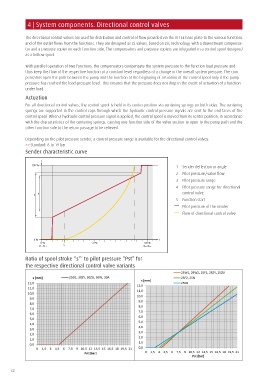
Depending on the pilot pressure sender, a control pressure range is available for the directional control valves:
>> Standard: 6 to 19 bar
Sender characteristic curve
2
100 %
1 Sender deflection or angle
2 Pilot pressure/valve flow
3 Pilot pressure range
4 Pilot pressure range for directional
3 4 control valve
5 Function start
Pilot pressure of the sender
Flow of directional control valve
0 % 1
0 % 50 % 100 %
5
Ratio of spool stroke “s”‘ to pilot pressure “Pst” for
the respective directional control valve variants
32