
Page 6 - Exlar - K series medium force roller screw actuator
P. 6
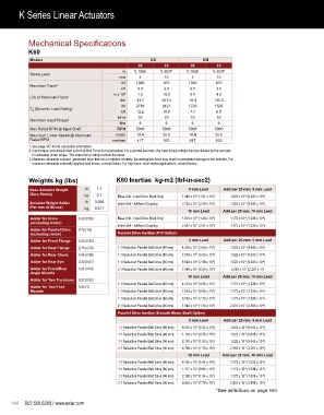
K Series Linear Actuators
Mechanical Specifications
K60
Models KX KM
05 10 05 10
in 0.1969 0.3937 0.1969 0.3937
Screw Lead
mm 5 10 5 10
lbf 1350 675 1350 675
Maximum Force 3
kN 6.0 3.0 6.0 3.0
in x 10 6 1.6 18.2 0.4 4.5
Life at Maximum Force 1
km 41.7 461.4 10.4 115.3
lbf 2738 2421 1725 1525
C (Dynamic Load Rating) kN 12.2 10.8 7.7 6.8
a
lbf-in 53 53 53 53
Maximum Input Torque 2
Nm 6 6 6 6
Max Rated RPM @ Input Shaft RPM 5000 5000 5000 5000
Maximum Linear Speed @ Maximum in/sec 16.4 32.8 16.4 32.8
Rated RPM mm/sec 417 833 417 833
1. See page 147 for life calculation information.
2. Input torque should be limited such that Max Force is not exceeded. For a parallel belt ratio, the input torque ratings must be divided by the belt ratio
for allowable motor torque. The output force ratings remain the same.
3. Maximum allowable actuator–generated force that can be applied routinely. Exceeding this force may result in permanent damage to the actuator. For
maximum allowable externally-applied axial forces, consult factory. For high force, short stroke applications, consult factory.
Weights kg (lbs) K60 Inertias kg-m2 (lbf-in-sec2)
Base Actuator Weight lb 1.7 5 mm Lead Add per 25 mm, 5 mm Lead
(Zero Stroke) kg 3.7 Base Unit - Input Drive Shaft Only 1.480 x 10 (1.31 x 10 ) 1.022 x 10 (9.045 x 10 )
-5
-4
-6
-6
Actuator Weight Adder lb 0.008 Inline Unit - w/Motor Coupling 2.702 x 10 (2.39 x 10 ) 1.022 x 10 (9.045 x 10 )
-4
-6
-5
-6
(Per mm of Stroke) kg 0.017
10 mm Lead Add per 25 mm, 10 mm Lead
-5
-5
-6
-4
Adder for Inline 0.42 (0.93) Base Unit - Input Drive Shaft Only 1.616 x 10 (1.43 x 10 ) 1.173 x 10 (1.038 x 10 )
(excluding motor) Inline Unit - w/Motor Coupling 2.837 x 10 (2.51 x 10 ) 1.173 x 10 (1.038 x 10 )
-5
-4
-6
-5
Adder for Parallel Drive 0.73 (1.6)
(excluding motor) Parallel Drive Inertias (P10 Option)
Adder for Front Flange 0.42 (0.93) 5 mm Lead Add per 25 mm, 5 mm Lead
-5
-6
-4
-6
Adder for Rear Flange 2.16 (4.79) 1:1 Reduction Parallel Belt Drive (66 mm) 4.339 x 10 (3.84 x 10 ) 1.022 x 10 (9.045 x 10 )
-6
-5
-6
Adder for Rear Clevis 0.44 (0.98) 1:1 Reduction Parallel Belt Drive (86 mm) 7.378 x 10 (6.53 x 10 ) 1.022 x 10 (9.045 x 10 )
-4
Adder for Rear Eye 0.30 (0.67) 1:1 Reduction Parallel Belt Drive (96 mm) 8.564 x 10 (7.58 x 10 ) 1.022 x 10 (9.045 x 10 )
-5
-4
-6
-6
Adder for Front/Rear 0.24 (0.54) 2:1 Reduction Parallel Belt Drive (96 mm) 7.095 x 10 (6.28 x 10 ) 2.555 x 10 (2.261 x 1 )
-7
-6
-4
-5
Angle Mounts
10 mm Lead Add per 25 mm, 10 mm Lead
Adder for Two Trunnions 0.37 (0.82)
1:1 Reduction Parallel Belt Drive (66 mm) 4.474 x 10 (3.96 x 10 ) 1.173 x 10 (1.038 x 10 )
-5
-5
-6
-4
Adder for Two Foot 0.45 (1)
Mounts 1:1 Reduction Parallel Belt Drive (86 mm) 7.514 x 10 (6.65 x 10 ) 1.173 x 10 (1.038 x 10 )
-5
-4
-6
-5
1:1 Reduction Parallel Belt Drive (96 mm) 8.704 x 10 (7.70 x 10 ) 1.173 x 10 (1.038 x 10 )
-5
-4
-6
-5
2:1 Reduction Parallel Belt Drive (96 mm) 1.966 x 10 (1.74 x 10 ) 2.931 x 10 (2.595 x 10 )
-7
-5
-6
-4
Parallel Drive Inertias (Smooth Motor Shaft Option)
5 mm Lead Add per 25 mm, 5 mm Lead
1:1 Reduction Parallel Belt Drive (66 mm) 6.015 x 10 (5.32 x 10 ) 1.022 x 10 (9.045 x 10 ) -6
-4
-5
-6
1:1 Reduction Parallel Belt Drive (86 mm) 1.103 x 10 (9.76 x 10 ) 1.022 x 10 (9.045 x 10 ) -6
-4
-4
-6
1:1 Reduction Parallel Belt Drive (96 mm) 2.176 x 10 (1.93 x 10 ) 1.022 x 10 (9.045 x 10 ) -6
-6
-4
-3
2:1 Reduction Parallel Belt Drive (96 mm) 8.768 x 10 (7.76 x 10 ) 2.555 x 10 (2.261 x 10 ) -6
-7
-5
-4
10 mm Lead Add per 25 mm, 10 mm Lead
1:1 Reduction Parallel Belt Drive (66 mm) 6.150 x 10 (5.44 x 10 ) 1.173 x 10 (1.038 x 10 ) -6
-5
-4
-6
1:1 Reduction Parallel Belt Drive (86 mm) 1.117 x 10 (9.88 x 10 ) 1.173 x 10 (1.038 x 10 ) -6
-4
-6
-4
1:1 Reduction Parallel Belt Drive (96 mm) 2.190 x 10 (1.94 x 10 ) 1.173 x 10 (1.038 x 10 ) -6
-3
-4
-6
2:1 Reduction Parallel Belt Drive (96 mm) 8.802 x 10 (7.79 x 10 ) 2.931 x 10 (2.595 x 10 ) -6
-7
-4
-5
*See definitions on page 143
144 952.500.6200 | www.exlar.com