
Page 22 - Parker - Coils and Electronics
P. 22
Catalog HY15-3502/US Proportional Valve Controller
Technical Information Series XPRO902rid, 932rid, 904rid, 934rid
CV
General Description
Proportional Valve Controllers. 12 and 24 Volts, PWM
with Multiple Adjustments. For additional information
see Technical Tips on pages CE1-CE2. Output LED I Max Adjustment
Check
Valves
SH 0 - 100%
Operation
The 902rid/932rid and 904rid/934rid are valve top
mounted PWM controllers for proportional control
Shuttle
Valves
valves. They can be used with an external potentiom-
LM
eter to give accurate current control using the units
internal reference voltage. Alternatively these control- Ramp Down Frequency
lers can be used with a 0-10V command signal from a
Ramp Up I min 0 - 50%
PLC or engine management system.
Load/Motor
Controls
FC ‘I’ Max adjustment is provided to allow the maximum
output current to be set via a 12 turn potentiometer.
Turn clockwise to increase the output current.
Ramp Up and Ramp Down adjustments provide
Flow
Controls
independent, linear control of the time it takes, to V
PC I
reach ‘I’ Max and to switch off, up to 8 seconds of
delay. Turn clockwise for slower ramps.
‘I’ Min adjustment Pot sets the minimum current the
controller will jump to when a command signal is
Pressure
Controls
LE present, used to eliminate dead band in a slow ramp. Features
Turn clockwise for a higher ‘I’ Min setting.
Dither adjustment Pot is used to alter the PWM • Self contained DIN ‘Plug Top’
frequency of the controller from 95 HZ to 230 Hz. By • High impact resistant molded ABS
Elements
changing the frequency this pot controls the amount of • Complies with current CE regulations
Logic
DC dither imposed on the valve. Lower frequency = more
dither, higher frequency = less dither. Turn clockwise to
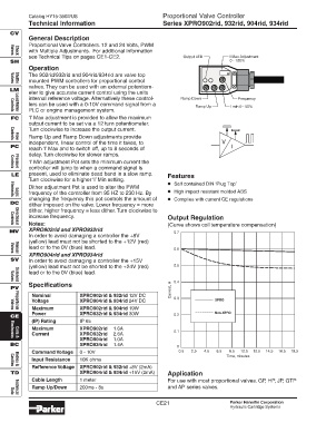
increase frequency. Output Regulation
Notes: (Curve shows coil temperature compensation)
Directional
Controls
XPRO902rid and XPRO932rid
MV 0.7
In order to avoid damaging a controller the +8V
(yellow) lead must not be shorted to the +12V (red)
lead or to the 0V (blue) lead. 0.6
XPRO904rid and XPRO934rid
Manual
Valves
SV In order to avoid damaging a controller the +15V
(yellow) lead must not be shorted to the +24V (red) 0.5
lead or to the 0V (blue) lead.
Solenoid
Valves
Specifications 0.4
PV Current, A
Nominal XPRO902rid & 932rid 12V DC 0.3
Voltage XPRO904rid & 934rid 24V DC XPRO
Maximum XPRO902rid & 904rid 19W
Proportional
Valves
Power XPRO932rid & 934rid 30W 0.2 Non-XPRO
CE
(IP) Rating IP 65
Maximum XPRO902rid 1.6A
0.1
Current XPRO932rid 2.6A
XPRO904rid 1.0A
Coils &
Electronics
BC XPRO934rid 1.4A
0
Command Voltage 0 - 10V 0.5 2.5 4.5 6.5 8.5 10.5 12.5 14.5 16.5 18.5
Time, minutes
Input Resistance 10K ohms
Refference Voltage XPRO902rid & 932rid +8V (2mA)
Bodies &
Cavities
TD XPRO904rid & 934rid +15V (2mA) Application
Cable Length 1 meter For use with most proportional valves. GP, HP, JP, GTP
Ramp Up/Down 200ms - 8s and AP series valves.
Technical
Data
CE21 Parker Hannifin Corporation
Hydraulic Cartridge Systems