
Page 7 - Proportion-Air - F-series Electro-Pneumatic Flow Monitor
P. 7
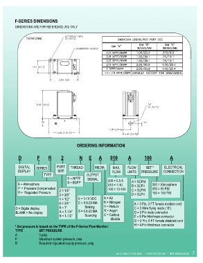
F-SERIES DIMENSIONS
          DIMENSIONS ARE FOR REFERENCE USE ONLY


                 Inches (mm)


                                               ORDERING INFORMATION


             D             F       R        2             N  E      A       010      A           100               A


            DIGITAL    SERIES      PORT     THREAD        MEDIA      MAX.     FLOW       SET ¹      ELECTRICAL
            DISPLAY                 SIZE                             FLOW     UNITS    PRESSURE     CONNECTION
                            TYPE                     OUTPUT
                                          N = NPTF    SIGNAL      005 = 0.5-5
            A = Atmosphere                B = BSPP                010 = 1-10    A = SCFM     000 = Atmosphere
                                                                                B = SCFH
            P  = Pressure Compensated                             100 = 10-100   C = SLPM    050 = 50 PSI
            R =  Regulated Pressure   2 = 1/4”                                               100 = 100 PSI
                                     3 = 3/8”                                   D = SLPH
                                     4 = 1/2”   E = 1-10 VDC    A = Air
                                     6 = 3/4 “   C = 5.6-20 MA    N = Nitrogen    A = 3 Pin, 3 FT female molded cord
          D = Digital display        8 = 1”             Sinking   H = Helium      C = 3 Wire flying leads (18”)
          BLANK = No display         A = 1-1/4”   S = 5.6-20 MA   R = Argon       D = 3 Pin male connector
                                     B = 1-1/2”           Sourcing   C = Carbon    E = 6 Pin Hirshman connector
                                                                        dioxide   G = 3 Pin, 6 FT female shielded cord
          ¹ Set pressure is based on the TYPE of the F-Series Flow Monitor:       H = 4 Pin Hirshman connector
          TYPE           SET PRESSURE
          A              0 psig
          P              Maximum system pressure, psia
          R              Required regulated supply pressure, psig

                                                                       LET’S TALK 317-335-2602   *   PROPORTION-AIR   *   BRF-SERIES0405E   7