
Page 147 - Wieland - Selos/Fasis
P. 147
facts & data
Mounting rails
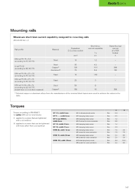
Maximum short-time current capability assigned to mounting rails
DIN EN 60 947-7-2
Short-time- Rated thermal
Equivalent current capability current
Rail profile Material
E-Cu cross section of a PEN
1 s busbar
mm 2 kA A
DIN rail TH 15 x 5,5 Steel 10 1.2 –
according to IEC 60 715
Steel 35 4.2 –
G rail TS 32 Copper 1) 120 14.4 269
according to IEC 60 715
Aluminium 1) 70 8.4 192
DIN rail TS 35 x 27 x 7,5 Steel 16 1.92 –
according to IEC 60 715
DIN rail TS 35 x 27 x 15 Steel 25 3 –
according to IEC 60 715
DIN rail TS 35 x 24 x 15 Steel 50 6 –
according to IEC 60 715
(made from 2.3 mm thick material) Copper 1) 150 18 309
1) Selected copper or aluminum alloys from the manufacturer of the terminal block layout were used to achieve the values in the
table.
Torques
II III
Torque according to EN 60947-1 WT 2.5, width 5 mm M2.5 clamping body screw Nm 0.4
for selos DIN rail terminal blocks
WT 4 … , width 6 mm M3 clamping body screw Nm 0.5
II applies for screws that are tightened WT 6 and WKN 6, M4 clamping body screw Nm 1.2
with a screwdriver
width 8 mm M3.5 screw for cross connector Nm 0.8
III applies for screws that can be tightened WT 10, width 10 mm M4 clamping body screw Nm 1.2
with tools other than a screwdriver
WT 16, width 12 mm M5 clamping body screw Nm 2.0
WKN 35, width 16 mm M6 clamping body screw Nm 2.5 3.0
M5 screw for cross connector Nm 2.0 2.0
WKN 70, width 24 mm M8 clamping body screw Nm 3.5 6.0
M6 screw for cross connector Nm 2.5 3.0
WKN 150, width 28 mm M10 clamping body screw Nm 4.0 10.0
M8 screw for cross connector Nm 3.5 6.0
147