
Page 28 - Wieland - Selos/Fasis
P. 28
Sicherungsklemmen mit Schraubanschluss
selos
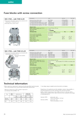
Fuse blocks with screw connection
WK 4 TKG... with THSi 5 x 20 Description Type Part No. Std. Pack
Disconnect base block, gray WK 4 TKG/U 57.504.4055.0 100
• Disconnect base block with screw connection for
mounting on TS 35 and TS 32 Fuse disconnect lever, gray THSI 5x20 Z1.298.1053.0 10
Fuse disconnect lever with LED 12 - 24 V 2) THSI 5x20 LED24 Z1.298.1153.0 10
• Nominal cross section 4 mm 2 Fuse disconnect lever with LED 24 - 60 V 2) THSI 5x20 LED60 Z1.298.1253.0 10
Fuse disconnect lever with GL 110 - 250 V 2) THSI 5x20 GL250 Z1.298.1353.0 10
General data
Width / length / height, incl. TS 7.5 6 mm / 48 mm / 81 mm
Wire strip length 9 mm
Approvals EMD'
Technical data IEC UL CSA
EN 60 947-7-1, EN 60 127-6
Cross section fine-stranded 0.5 – 4 mm 2
Cross section solid/stranded 0.5 – 6 mm 2
Cross section, AWG 22 – 10 20 – 10
Rated current 1) 10 A 1) 6.3 A 1)
Rated voltage 690 V 2) 300 V 2) 250 V 2)
Rated impulse voltage 6 kV
Pollution degree 3
WK 4 TKG... with THSi 6,3 x 32 Description Type Part No. Std. Pack
Disconnect base block, gray WK 4 TKG/U 57.504.4055.0 100
• Disconnect base block with screw connection for
mounting on TS 35 and TS 32 Fuse disconnect lever, gray THSI 6,3x32 Z1.298.1653.0 10
Fuse disconnect lever with LED 12 - 24 V 2) THSI 6,3x32 LED24 Z1.298.1753.0 10
• Nominal cross section Fuse disconnect lever with LED 24 - 60 V 2) THSI 6,3x32 LED60 Z1.298.1853.0 10
4 mm 2 2)
Fuse disconnect lever with GL 110 - 250 V THSI 6,3x32 GL250 Z1.298.1953.0 10
General data
Width / length / height, incl. TS 7.5 6 mm / 48 mm / 81 mm
Width disconnect lever THSI 6.3x32 8 mm use end plate 07.311.6155.0 to maintain pitch
Wire strip length 9 mm
Approvals EMD'
Technical data IEC UL CSA
EN 60 947-7-1, EN 60 127-6
Cross section fine-stranded 0.5 – 4 mm 2
Cross section solid/stranded 0.5 – 6 mm 2
Cross section, AWG 22 – 10 20 – 10
Rated current 1) 10 A 1) 6.3 A 1)
Rated voltage 690 V 2) 300 V 2) 250 V 2)
Rated impulse voltage 6 kV
Pollution degree 3
Technical information:
1) When selecting G fuse inserts, make sure that the specified maximum power 2) The voltage range is determined by the built-in LED display.
loss is not exceeded. The current is determined by the inserted fuse.
Maximum power loss at 23° C ambient temperature Depending on the application and the installation method, the possibility of
(according to DIN EN 60947-7-3) increased temperature must be checked in the closed fuse holders.
Higher ambient temperatures mean additional stress for the fuse inserts.
Therefore, the reduction of the rated current must be considered accordingly
Rated Exclusive short-
Type Overload protection in these applications.
Voltage circuit protection
Single Group Single Group
arrangement arrangement arrangement arrangement Indicator (24 V): Lamp color: red
THSI 5 x 20 250 V 2.5 W 1.6 W 4.0 W 2.5 W Power consumption: 10.3 mA
THSI 6,3 x 32 500 V 2.5 W 1.6 W 4.0 W 4.0 W Indicator (220 V): Lamp color: red
Power consumption: 0.3 mA
SIST 250 V 2.5 W 1.6 W 2.5 W 2.5 W
28 More accessories page 124 ff.