Page 304 - Mechatronics with Experiments
P. 304

JWST499-Cetinkunt
            JWST499-c05
                       290   MECHATRONICS  Printer: Yet to Come                     October 28, 2014 11:15 254mm×178mm
                              would vary between
                                                  (        1           )
                                         V = K diff  V diff  +  ⋅ V common                      (5.200)
                                           o
                                                         CMMR
                                                               5
                                         V = 100 ⋅ (10 mV + (1∕10 ) ⋅ 0.0) = 1V; when V = 10 mV  (5.201)
                                           o
                                                                                  i
                                                               5
                                         V = 100 ⋅ (10 mV + (1∕10 ) ⋅ 100 mV) = 1.0001 V        (5.202)
                                           o
                                              ; when V = (10 + 100) mV                          (5.203)
                                                     i
                              Clearly, the differential-ended signal and op-amp are able to amplify the desired portion of
                              the signal and attenuate very effectively the noise portion of the signal. The key assumption
                              for this to work is that the same noise signal is induced on both conductors (both inputs of
                              the differential amplifier).
                              5.6.2 Common Op-Amp Circuits

                              Op-amps are used in both open loop and closed loop configurations. Various op-amp
                              circuits for specific functions are discussed below: comparator, inverting and non-inverting
                              amplifier, sum, derivative, integral, and various filters.

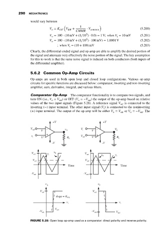
                              Comparator Op-Amp       The comparator functionality is to compare two signals, and
                              turn ON (i.e., V = V )orOFF(V =−V ) the output of the op-amp based on relative
                                           o   sat        o     sat
                              values of the two input signals (Figure 5.28). A reference signal V  is connected to the
                                                                                    ref
                              inverting (−) input terminal. The other input signal (V ) is connected to the noninverting
                                                                          i
                              (+) input terminal. The output of the op-amp will be either V = V  or V =−V .The
                                                                               o    sat   o     sat
                                           +V                            +V
                              V ref  V  -  _       v 0      V i    V  -  _      V 0

                              v i   V  +  +         R L     V ref  V  +  +        R L
                                           -V                            -V


                              V sat     v i  v 0              V sat     v 0      v i

                               V ref                           V ref
                                                    Time                            Time

                              -V sat                          -V sat


                                       v                              v
                                        0                              0
                                    V sat                          V sat
                                             slope = K 0 L

                                                   v i                             v i
                                             V
                                   -V sat     ref                  -V sat        V ref


                              FIGURE 5.28: Open loop op-amp used as a comparator: direct polarity and reverse polarity.
   299   300   301   302   303   304   305   306   307   308   309