
Page 307 - Mechatronics with Experiments
P. 307
October 28, 2014 11:15 254mm×178mm
Printer: Yet to Come
JWST499-c05
JWST499-Cetinkunt
ELECTRONIC COMPONENTS FOR MECHATRONIC SYSTEMS 293
R 1 v ref, h
-
+
V in v out
-
v ref, l
R +
1
v out
v in
v v
ref, l ref, h
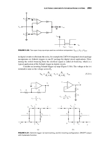
FIGURE 5.30: Two open loop op-amps used as a window comparator: V ref,l ≤ V in ≤ V ref,h .
in digital circuits to eliminate the noise, for example the LM7414 integrated circuit package
incorporates six Schmitt triggers in one IC package for digital circuit applications. Elim-
inating the switch bouncing from the electrical signal is called de-bouncing, which is a
typical application of the Schmitt trigger in digital circuits.
Consider an inverting Schmitt trigger op-amp (Figure 5.31b). The voltage at the (+)
terminal is same as the voltage across R ,
2
R 2 R 2
V = ⋅ V = ⋅ V sat (5.211)
o
R + R 2 R + R 2
R 2
1
1
V
_ V o i _ V o
v + + +
v +
V i R i R f R 1
R 2
R 2
R V = V sat
T
V = i V R 1 + R 2
T sat
R
f
v
v o o
V A V
D sat C sat
-V V -V V
T T T T
v v i
i
B B
A - V D - V
sat
sat
C
(a) (b)
FIGURE 5.31: Schmitt trigger: (a) noninverting, and (b) inverting configuration. ON/OFF output
with hysteresis function.