
Page 311 - Mechatronics with Experiments
P. 311
October 28, 2014 11:15 254mm×178mm
Printer: Yet to Come
JWST499-Cetinkunt
JWST499-c05
ELECTRONIC COMPONENTS FOR MECHATRONIC SYSTEMS 297
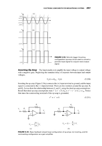
v (a)
v (b)
v
(c)
FIGURE 5.33: Schmitt trigger (inverting
configuration) op-amp circuit used to convert a
periodic input signal to a square wave output
signal.
Inverting Op-Amp The functionality is to amplify the input voltage to output voltage
with a negative gain. Neglecting the transient delay of response between input and output
voltages,
V (t) = K ⋅ V (t) (5.230)
o CL i
Inverting the op-amp (Figure 5.34a) connects the (+) input terminal to ground, and the input
signal is connected to the (−) input terminal. There are two resistors around the op-amp: R i
and R . Let us show the relationship between V and V using the ideal op-amp assumptions.
f i o
−
+
+
−
Recall that ideal op-amp assumptions state i = i = 0, E = v − v = 0, i = i . Notice
d f in
that since the noninverting terminal of the op-amp is grounded,
−
+
v = v = 0 (5.231)
R R
f f
V R R
i i i
_ V o _ V o
v + + V i +
R
R
+
f
V = − ( ) V i V = 1 ( ) V i
f
R
O
O
i
R i
(a) (b)
FIGURE 5.34: Basic feedback (closed loop) configuration of op-amps: (a) inverting, and (b)
noninverting configuration as a gain amplifier.