
Page 348 - Mechatronics with Experiments
P. 348
JWST499-Cetinkunt
JWST499-c06
334 MECHATRONICS Printer: Yet to Come October 9, 2014 8:1 254mm×178mm
R 2
I
A V i
R m V o R 1
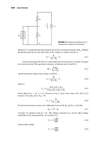
FIGURE 6.7: Electrical loading error in
B
measurement systems and sensors.
(Figure 6.7). Assume that the measurement device has an internal resistance of R . Without
m
the measurement device, the ideal value of the voltage we want to measure is
R 1
∗
V = ⋅ V (6.2)
o i
R + R 2
1
Once the measurement device is connected to the circuit at points A and B, it changes
the electrical circuit. The equivalent resistance in between point A and B is
R R
1 m
∗
R = (6.3)
1
R + R m
1
and the measured voltage across points A and B is
R ∗ 1
V = ∗ ⋅ V i (6.4)
o
R + R 2
1
which is
R R ∕(R + R )
m
1
1 m
V = V i (6.5)
o
R R ∕(R + R ) + R 2
1
m
1 m
∗
Notice that as R → ∞, V = V . However, if R is close to the value of R ,the V ∕V ∗ o
m
o
1
m
o
o
deviates from unity, that is R = R 1
m
R 1
V = V (6.6)
o i
R + 2R
1 2
In most measurement systems, the relationship between the R and R is such that
1
m
3
R = 10 ⋅ R 1 (6.7)
m
Consider for simplicity that R = R . The voltage measured (V ) and the ideal voltage
1
2
o
∗
should have been measured if R was infinity (V ),
m
o
1000
V = V (6.8)
o i
2001
and the ideal voltage
1000
∗
V = V (6.9)
o i
2000