
Page 350 - Mechatronics with Experiments
P. 350
JWST499-Cetinkunt
JWST499-c06
336 MECHATRONICS Printer: Yet to Come October 9, 2014 8:1 254mm×178mm
R 1
B
i m
i 1
R
2
Sensor
i 3
A D
R m V o
i
i 3 4
Measurement
R 3 R 4 device (i.e. ADC,
DMM)
i
C m
V i
DC power supply
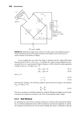
FIGURE 6.8: Wheatstone bridge circuit, which is very often used in many different types of
sensor applications as part of the signal conditioner and amplifier circuit of the sensor, to
convert variation in the resistor to voltage.
Let us consider the case where the bridge is balanced and the voltage differential
between points B and C is zero (V = 0) and that the current passing through the mea-
BC
surement device (i.e., galvonometer, digital voltmeter, or ADC circuit for a data acquisition
system) is zero (i = 0). Since V BC = 0,
m
i R − i R = 0 (6.21)
1 1
3 3
i R − i R = 0 (6.22)
4 4
2 2
and i = 0,
m
i = i 2 (6.23)
1
i = i 4 (6.24)
3
Solving these equations, the following relations must hold for the bridge to be balanced
(V BC = 0 and i = 0),
m
R R
1 3
= (6.25)
R 2 R 4
Now, let us examine two different methods for using the Wheatstone bridge circuit in order
to measure the variation in resistance in the form of proportional output voltage.
6.3.1 Null Method
R represents the sensor whose resistance changes as a function of the measured variable.
1
R is a calibrated adjustable resistor (either manually or automatically adjusted). R and R 4
3
2
are resistances fixed and known for the circuit. Initially the circuit is calibrated so that the