
Page 354 - Mechatronics with Experiments
P. 354
JWST499-Cetinkunt
JWST499-c06
340 MECHATRONICS Printer: Yet to Come October 9, 2014 8:1 254mm×178mm
Element Cold platted terminals
and continuity bar
Countinuity
strip
Housing
Anti-backlash Element Brass bushing
Gold plated
wave washer
terminals:
Housing Guide rails
Stainless
steel shaft
Stainless steel
shaft
Predious metal wiper
Presious metal wiper
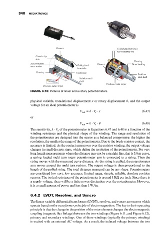
FIGURE 6.10: Pictures of linear and a rotary potentiometers.
physical variable, translational displacement x or rotary displacement , and the output
voltage for an ideal potentiometer is
V out = k ⋅ V ⋅ x (6.47)
r
or
V = k ⋅ V ⋅ (6.48)
out r
The sensitivity, k ⋅ V of the potentiometer in Equations 6.47 and 6.48 is a function of the
r
winding resistance and the physical shape of the winding. The range and resolution of
the potentiometer are designed into the sensor as a balanced compromise: the higher the
resolution, the smaller the range of the potentiometer. Due to the brush-resistor contact, the
accuracy is limited. As the contact arm moves over the resistor winding, the output voltage
changes in small discrete steps, which define the resolution of the potentiometer. For very
long length measurements where the distance may not be a straight line, that is 5.0 m curve,
a spring loaded multi turn rotary potentiometer arm is connected to a string. Then the
string moves with the measured curve distance. As the string is pulled, the potentiometer
arm moves around the multi turn resistor. The output voltage is then proportional to the
length of the pulled string. The total distance measured can be any shape. Potentiometers
are considered low cost, low accuracy, limited range, simple, reliable, absolute position
sensors. The typical resistance of the potentiometer is around 1 KΩ per inch. Since there is
a supply voltage, there will be a finite power dissipation over the potentiometer. However,
it is a small amount of power and less than 1 W∕in.
6.4.2 LVDT, Resolver, and Syncro
The linear variable differential transformer (LVDT), resolver, and syncro are sensors which
operate based on the transformer principle of electromagnetism. The key to their operating
principle is that the change in the position of the rotor element changes the electromagnetic
coupling (magnetic flux linkage) between the two windings (Figure 6.11, and Figure 6.12),
primary and secondary windings. One of these windings (typically the primary winding)
is excited with an external AC voltage. As a result, the induced voltage between the two