Page 356 - Mechatronics with Experiments
P. 356

JWST499-Cetinkunt
            JWST499-c06
                       342   MECHATRONICS  Printer: Yet to Come                       October 9, 2014 8:1  254mm×178mm
                              steel rod is used to connect the core to the part whose displacement is to be measured. The
                              sign (direction) of the magnitude of the voltage differential is determined by relating the
                              induced voltage phase to the reference voltage phase. It is a function of the direction of
                              the magnetic core displacement from neutral position. The primary winding is excited by
                                                          V (t) = V ⋅ sin(w t)                   (6.49)
                                                                        r
                                                                 r
                                                           p
                              and the voltage differential between the secondary windings is
                                                      V (t) = k ⋅ V (t) ⋅ x(t)                   (6.50)
                                                             0
                                                                 p
                                                       s
                                                          = k ⋅ V ⋅ sin(w t) ⋅ x(t)              (6.51)
                                                             0
                                                                 r
                                                                       r
                              Once the the V (t) is demodulated in frequency, the output signal is presented as a DC
                                          s
                              voltage,
                                                           V out (t) = k ⋅ x(t)                  (6.52)
                                                                   1
                              which is proportional to the core displacement.
                                   LVDTs can be used for high resolution position measurement (i.e., 1∕10 000 in res-
                              olution) but with a relatively small range (up to 10 in range). Excitation frequency of the
                              primary coil is in the range of 50 Hz to 25 kHz. The bandwidth of the sensor is about 1∕10
                              of the excitation frequency (Figure 6.12).
                                   The resolver (Figure 6.13) and syncro (Figure 6.16) sensors operate on the same
                              principle as the LVDT. Resolvers compete with encoders in position measurement applica-
                              tions. In general, resolvers have better mechanical ruggedness, but lower bandwidth than the
                              encoders. Resolvers have two stator windings (90 degrees out of phase), whereas syncros
                              have three stator windings (120 degrees out of phase).
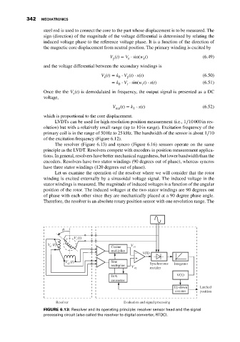
                                   Let us examine the operation of the resolver where we will consider that the rotor
                              winding is excited externally by a sinusoidal voltage signal. The induced voltage in the
                              stator windings is measured. The magnitude of induced voltages is a function of the angular
                              position of the rotor. The induced voltages at the two stator windings are 90 degrees out
                              of phase with each other since they are mechanically placed at a 90 degree phase angle.
                              Therefore, the resolver is an absolute rotary position sensor with one revolution range. The


                                                          Cosine
                                                          multiplier
                                                                       VFD
                                                          Sine             Synchronous
                                                          multiplier                 Integrator
                                                                           rectifier
                                                          D/A                         VCO
                                                          converter
                                                                                     Up-down    Latched
                                                                                     counter    position

                                   Resolver                     Evaluation and signal processing
                              FIGURE 6.13: Resolver and its operating principle: resolver sensor head and the signal
                              processing circuit (also called the resolver to digital converter, RTDC).
   351   352   353   354   355   356   357   358   359   360   361