
Page 360 - Mechatronics with Experiments
P. 360
JWST499-Cetinkunt
JWST499-c06
346 MECHATRONICS Printer: Yet to Come October 9, 2014 8:1 254mm×178mm
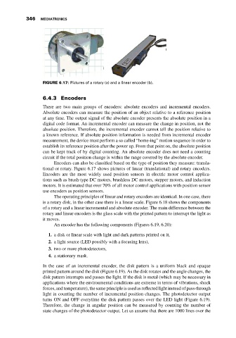
FIGURE 6.17: Pictures of a rotary (a) and a linear encoder (b).
6.4.3 Encoders
There are two main groups of encoders: absolute encoders and incremental encoders.
Absolute encoders can measure the position of an object relative to a reference position
at any time. The output signal of the absolute encoder presents the absolute position in a
digital code format. An incremental encoder can measure the change in position, not the
absolute position. Therefore, the incremental encoder cannot tell the position relative to
a known reference. If absolute position information is needed from incremental encoder
measurement, the device must perform a so called “home-ing” motion sequence in order to
establish its reference position after the power up. From that point on, the absolute position
can be kept track of by digital counting. An absolute encoder does not need a counting
circuit if the total position change is within the range covered by the absolute encoder.
Encoders can also be classified based on the type of position they measure: transla-
tional or rotary. Figure 6.17 shows pictures of linear (translational) and rotary encoders.
Encoders are the most widely used position sensors in electric motor control applica-
tions such as brush-type DC motors, brushless DC motors, stepper motors, and induction
motors. It is estimated that over 70% of all motor control applications with position sensor
use encoders as position sensors.
The operating principles of linear and rotary encoders are identical. In one case, there
is a rotary disk, in the other case there is a linear scale. Figure 6.18 shows the components
of a rotary and a linear incremental and absolute encoder. The main difference between the
rotary and linear encoders is the glass scale with the printed pattern to interrupt the light as
it moves.
An encoder has the following components (Figures 6.19, 6.20):
1. a disk or linear scale with light and dark patterns printed on it,
2. a light source (LED possibly with a focusing lens),
3. two or more photodetectors,
4. a stationary mask.
In the case of an incremental encoder, the disk pattern is a uniform black and opaque
printed pattern around the disk (Figure 6.19). As the disk rotates and the angle changes, the
disk pattern interrupts and passes the light. If the disk is metal (which may be necessary in
applications where the environmental conditions are extreme in terms of vibrations, shock
forces, and temperature), the same principle is used as reflected light instead of pass-through
light in counting the number of incremental position changes. The photodetector output
turns ON and OFF everytime the disk pattern passes over the LED light (Figure 6.19).
Therefore, the change in angular position can be measured by counting the number of
state changes of the photodetector output. Let us assume that there are 1000 lines over the