
Page 364 - Mechatronics with Experiments
P. 364
JWST499-Cetinkunt
JWST499-c06
350 MECHATRONICS Printer: Yet to Come October 9, 2014 8:1 254mm×178mm
Channel A
Channel B
X1
X2
X4
Ch A
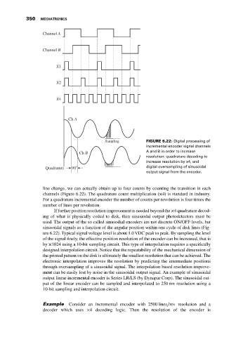
Sampling FIGURE 6.22: Digital processing of
incremental encoder signal channels
Ch B A and B in order to increase
resolution: quadrature decoding to
increase resolution by x4, and
Quadrature 90° digital oversampling of sinusoidal
output signal from the encoder.
line change, we can actually obtain up to four counts by counting the transition in each
channels (Figure 6.22). The quadrature count multiplication (×4) is standard in industry.
For a quadrature incremental encoder the number of counts per revolution is four times the
number of lines per revolution.
If further position resolution improvement is needed beyond the ×4 quadrature decod-
ing of what is physically coded to disk, then sinusiodal output photodetectors must be
used. The output of the so called sinusodial encoders are not discrete ON/OFF levels, but
sinusoidal signals as a function of the angular position within one cycle of disk lines (Fig-
ure 6.22). Typical signal voltage level is about 1.0 VDC peak to peak. By sampling the level
of the signal finely, the effective position resolution of the encoder can be increased, that is
by ×1024 using a 10-bit sampling circuit. This type of interpolation requires a specifically
designed interpolation circuit. Notice that the repeatability of the mechanical dimension of
the printed pattern on the disk is ultimately the smallest resolution that can be achieved. The
electronic interpolation improves the resolution by predicting the intermediate positions
through oversampling of a sinusoidal signal. The interpolation based resolution improve-
ment can be easily lost by noise in the sinusoidal output signal. An example of sinusoidal
output linear incremental encoder is Series LR/LS (by Dynapar Corp). The sinusoidal out-
put of the linear encoder can be sampled and interpolated to 250 nm resolution using a
10-bit sampling and interpolation circuit.
Example Consider an incremental encoder with 2500 lines∕rev resolution and a
decoder which uses ×4 decoding logic. Then the resolution of the encoder is