
Page 368 - Mechatronics with Experiments
P. 368
JWST499-Cetinkunt
JWST499-c06
354 MECHATRONICS Printer: Yet to Come October 9, 2014 8:1 254mm×178mm
Hence, there is a relationship between the measurable current effort and capacitance. The
excitation circuit which maintains the constant capacitance by controlling the current uses
a high frequency modulation signal (i.e., 20 KHz modulation frequency).
The resolution of the capacitive gap sensor is typically in the micrometer range
(1 μm = 10 −6 m), but it can be made as low as a few nanometers (1 nm == 10 −9 m) for
special applications. The range is limited to about 10 mm. The frequency response of specific
capacitive sensors can vary as a function of the sensed gap distance. The bandwidth of a
given sensor varies as a function of the gap measured as a percentage of its total range. The
smaller the gap distance measured relative to the sensor range, the higher the bandwidth of
the sensor. For instance, a non-contact capacitive gap sensor can have 1000 Hz bandwidth
for measuring gap distances within 10% of its range, while the same sensor may have about
100 Hz bandwidth while measuring gap distances around 80% of its range.
Capacitive presence sensors provide only two state ON/OFF output, and sense the
change in the oscillator circuit signal amplitude. When a target object enters the field
sensing distance of the sensor, the capacitance increases and the magnitude of oscillations
increases. A detection and output circuit then controls the ON/OFF state of a transistor.
The capacitive gap sensor can also be used to sense the presence, density, and
thickness of non-conducting objects. The non-conductor materials (such as epoxy, PVC,
glass) which have a different dielectric constant than air can be detected since the presence
of a such material in front of the probe instead of air results in a change in the capacitance.
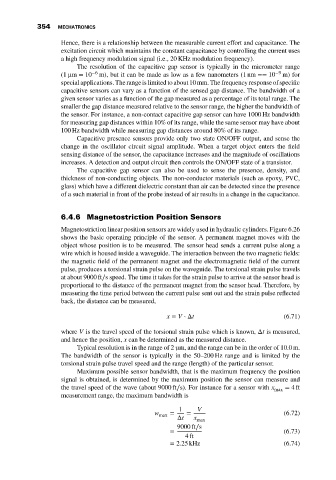
6.4.6 Magnetostriction Position Sensors
Magnetostriction linear position sensors are widely used in hydraulic cylinders. Figure 6.26
shows the basic operating principle of the sensor. A permanent magnet moves with the
object whose position is to be measured. The sensor head sends a current pulse along a
wire which is housed inside a waveguide. The interaction between the two magnetic fields:
the magnetic field of the permanent magnet and the electromagnetic field of the current
pulse, produces a torsional strain pulse on the waveguide. The torsional strain pulse travels
at about 9000 ft∕s speed. The time it takes for the strain pulse to arrive at the sensor head is
proportional to the distance of the permanent magnet from the sensor head. Therefore, by
measuring the time period between the current pulse sent out and the strain pulse reflected
back, the distance can be measured,
x = V ⋅ Δt (6.71)
where V is the travel speed of the torsional strain pulse which is known, Δt is measured,
and hence the position, x can be determined as the measured distance.
Typical resolution is in the range of 2 μm, and the range can be in the order of 10.0m.
The bandwidth of the sensor is typically in the 50–200 Hz range and is limited by the
torsional strain pulse travel speed and the range (length) of the particular sensor.
Maximum possible sensor bandwidth, that is the maximum frequency the position
signal is obtained, is determined by the maximum position the sensor can measure and
the travel speed of the wave (about 9000 ft∕s). For instance for a sensor with x = 4ft
max
measurement range, the maximum bandwidth is
1 V
w max = = (6.72)
Δt x max
9000 ft∕s
= (6.73)
4ft
= 2.25 kHz (6.74)