
Page 372 - Mechatronics with Experiments
P. 372
JWST499-Cetinkunt
JWST499-c06
358 MECHATRONICS Printer: Yet to Come October 9, 2014 8:1 254mm×178mm
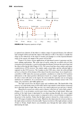
Violet Yellow Near infrared
Blue Green Orange Red
400 nm 500 nm 600 nm 700 nm 800 nm
Visible light
X-rays Ultraviolet Infrared
1 nm 10 nm 100 nm 1 μ 10 μ 100 μ 1 mμ
FIGURE 6.30: Frequency spectrum of light.
is captured on a detector. If the object is within a range of expected distance, the reflected
light strength will be such that the output of the detector is ON. If the object is outside that
range (or the reflectivity of the object is weaker even though it is in the expected distance
range of the sensor), the output of the sensor will be OFF.
Figure 6.31a shows various applications of light-based sensors in presence and dis-
tance sensing applications. The same type of sensor, using the so-called reflected light
triangularization principle, is used in measuring the distance between the sensor head and
the object reflecting the light (Figure 6.31b). The sensor head has a laser emitter and charge
coupled device (CCD) receiver. The emitter sends a laser light, and the reflected light is
captured on the CCD receiver. The location on the CDD array where the reflected light
arrives is a function of the distance of the object from the sensor head. An on-board micro-
controller or DSP makes the necessary geometric calculations to relate the CCD position
information to the object position information based on a simple trigonometric relation.
In order to deal with noise in the signal, the microcontroller typically uses an averaging
method in its calculations. It is common to have a laser based distance sensor with 1.0m
range, 10 μ resolution, and 4 kHz update rate.
The light sensors have the largest range and resolution ratio. The bandwidth of the
sensor is very high (in the order of a few kHz) and it is not sensitive to the distance measured
due to the high speed of light. They are also very small in physical size and easy to install.
Photoelectric sensors are widely used in industry in the form of “safety light curtains”
(Figure 6.32). A set of emitter–receiver pairs forms a linear line of light beams. When any
portion of the light beam is interrupted by an object passing through, the sensor output
turns ON. Typically, the sensor output is connected to drive a circuit breaker to shutdown
the power to the machine. Notice that the light curtain is formed by a finite number (i.e.,
10 to 100 range) of emitter–receiver pairs. Therefore, the object must be at least as thick as
the light curtain resolution to be detectable. Typical resolution of the light curtain is around
25 mm to 30 mm. Small objects can potentially pass through the light curtain without
interrupting the light.