
Page 375 - Mechatronics with Experiments
P. 375
October 9, 2014 8:1
Printer: Yet to Come
JWST499-c06
JWST499-Cetinkunt
SENSORS 361 254mm×178mm
Electromagnetic
field
Electrical
coil
Oscillator Detector Output
Target
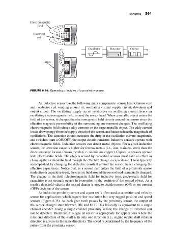
FIGURE 6.34: Operating principles of a proximity sensor.
An inductive sensor has the following main components: sensor head (ferrous core
and conductor coil winding around it), oscillating current supply circuit, detection and
output circuit. The oscillating supply circuit establishes an oscillating current, hence an
oscillating electromagnetic field, around the sensor head. When a metallic object enters the
field of the sensor, it changes the electromagnetic field density around the sensor since the
effective magnetic permeability of the surrounding environment changes. The oscillating
electromagnetic field induces eddy currents on the target metallic object. The eddy current
losses draw energy from the supply circuit of the sensor, and hence reduce the magnitude of
oscillations. The detection circuit measures the drop in the oscillation current magnitude,
and switches (turn a ON/OFF) the output circuit transistor. Inductive sensors operate with
electromagnetic fields. Inductive sensors can detect metal objects. For a given inductive
sensor, the detection range is higher for ferrous metals (i.e., iron, stainless steel) than the
detection range for non-ferrous metals (i.e., aluminum, copper). Capacitive sensors operate
with electrostatic fields. The objects sensed by capacitive sensors must have an effect in
changing the electrostatic field through the effective change in capacitance. This is typically
accomplished by changing the dielectric constant around the sensor, hence changing the
effective capacitance. Notice that, as a sensed part enters the field of a proximity sensor
(inductive or capacitive type), the electric field around the sensor head is gradually changed.
The change in the field (electromagnetic field for inductive type, electrostatic field for
capacitive type) strength occurs in proportion to the position of the sensed object. As a
result a threshold value in the sensed change is used to decide present (ON) or not-present
(OFF) decision of the sensor.
An inductive proximity sensor and a gear set is often used as a position and velocity
sensor for applications which require low resolution but very rugged position and speed
sensors (Figure 6.35). As each gear tooth passes by the proximity sensor, the output of
the sensor changes state between ON and OFF. This basically is equivalent to a single
channel encoder. Using a single channel proximity sensor, the change of direction can
not be detected. Therefore, this type of sensor is appropriate for applications where the
rotational direction of the shaft is in only one direction (i.e., engine output shaft rotation
direction is always in the same direction). The speed is determined by the frequency of the
pulses from the proximity sensor.