
Page 376 - Mechatronics with Experiments
P. 376
JWST499-Cetinkunt
JWST499-c06
362 MECHATRONICS Printer: Yet to Come October 9, 2014 8:1 254mm×178mm
0.005 to 0.030 in
(0.13 to 0.76 mm)
On/off
sensor
0.081 in min
(2.1 mm) Gear
FIGURE 6.35: Operating principles of a
0.081 in min proximity sensor (inductive, capacitive, Hall
(2.1 mm) 0.081 in min effect types) and a gear on a shaft to
(2.1 mm) measure rotary position and speed.
6.5 VELOCITY SENSORS
6.5.1 Tachometers
Construction of a tachometer is identical to the construction of a brush-type DC motor,
except that it is smaller in size since the tachometer is used for measurement purposes,
not for the purpose of converting electrical power to mechanical power like an electric
motor actuator. A tachometer involves a rotor winding, a permanent magnet stator and
commutator-brush assembly (Figure 6.36).
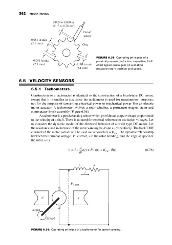
A tachometer is a passive analog sensor which provides an output voltage proportional
to the velocity of a shaft. There is no need for external reference or excitation voltages. Let
us consider the dynamic model of the electrical behavior of a brush type DC motor. Let
the resistance and inductance of the rotor winding be R and L, respectively. The back EMF
constant of the motor (which will be used as tachometer) is K . The dynamic relationship
vw
between the terminal voltage, V , current, i in the rotor winding, and the angular speed of
t
the rotor, w is
d
̇
0 = L ⋅ i(t) + R ⋅ i(t) + K vw ⋅ (t) (6.76)
dt
L R
i
V b emf
N S
Torque
Speed
FIGURE 6.36: Operating principle of a tachometer for speed sensing.