
Page 367 - Mechatronics with Experiments
P. 367
Printer: Yet to Come
October 9, 2014 8:1
JWST499-c06
JWST499-Cetinkunt
SENSORS 353 254mm×178mm
A+
A
A+
Target object
x x
B– A+ B–
B–
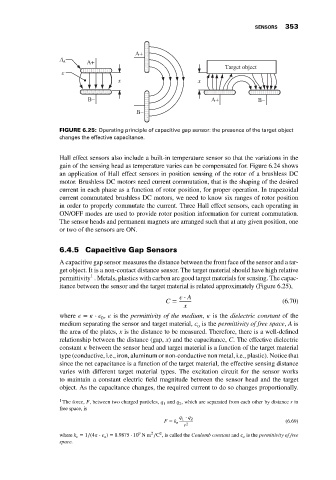
FIGURE 6.25: Operating principle of capacitive gap sensor: the presence of the target object
changes the effective capacitance.
Hall effect sensors also include a built-in temperature sensor so that the variations in the
gain of the sensing head as temperature varies can be compensated for. Figure 6.24 shows
an application of Hall effect sensors in position sensing of the rotor of a brushless DC
motor. Brushless DC motors need current commutation, that is the shaping of the desired
current in each phase as a function of rotor position, for proper operation. In trapezoidal
current commutated brushless DC motors, we need to know six ranges of rotor position
in order to properly commutate the current. Three Hall effect sensors, each operating in
ON/OFF modes are used to provide rotor position information for current commutation.
The sensor heads and permanent magnets are arranged such that at any given position, one
or two of the sensors are ON.
6.4.5 Capacitive Gap Sensors
A capacitive gap sensor measures the distance between the front face of the sensor and a tar-
get object. It is a non-contact distance sensor. The target material should have high relative
1
permittivity . Metals, plastics with carbon are good target materials for sensing. The capac-
itance between the sensor and the target material is related approximately (Figure 6.25),
⋅ A
C = (6.70)
x
where = ⋅ , is the permittivity of the medium, is the dielectric constant of the
0
medium separating the sensor and target material, is the permittivity of free space, A is
o
the area of the plates, x is the distance to be measured. Therefore, there is a well-defined
relationship between the distance (gap, x) and the capacitance, C. The effective dielectric
constant between the sensor head and target material is a function of the target material
type (conductive, i.e., iron, aluminum or non-conductive non metal, i.e., plastic). Notice that
since the net capacitance is a function of the target material, the effective sensing distance
varies with different target material types. The excitation circuit for the sensor works
to maintain a constant electric field magnitude between the sensor head and the target
object. As the capacitance changes, the required current to do so changes proportionally.
1
The force, F, between two charged particles, q and q , which are separated from each other by distance r in
2
1
free space, is
q 1 ⋅ q 2
(6.69)
F = k e
r 2
2
9
2
where k e = 1∕(4 ⋅ o ) = 8.9875 ⋅ 10 Nm ∕C , is called the Coulomb constant and o is the permittivity of free
space.