
Page 363 - Mechatronics with Experiments
P. 363
October 9, 2014 8:1
Printer: Yet to Come
JWST499-Cetinkunt
JWST499-c06
SENSORS 349 254mm×178mm
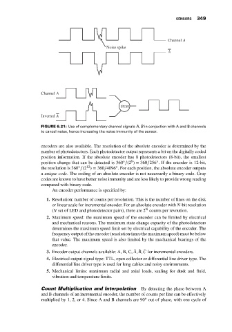
Channel A
Noise spike
A
Channel A
SUM
Inverted A
̄ ̄
FIGURE 6.21: Use of complementary channel signals A, B in conjuction with A and B channels
to cancel noise, hence increasing the noise immunity of the sensor.
encoders are also available. The resolution of the absolute encoder is determined by the
number of photodetectors. Each photodetector output represents a bit on the digitally coded
position information. If the absolute encoder has 8 photodetectors (8-bit), the smallest
◦
◦
8
position change that can be detected is 360 ∕(2 ) = 360∕256 . If the encoder is 12-bit,
◦
◦
12
the resolution is 360 ∕(2 ) = 360∕4096 . For each position, the absolute encoder outputs
a unique code. The coding of an absolute encoder is not necessarily a binary code. Gray
codes are known to have better noise immunity and are less likely to provide wrong reading
compared with binary code.
An encoder performance is specified by:
1. Resolution: number of counts per revolution. This is the number of lines on the disk
or linear scale for incremental encoder. For an absolute encoder with N-bit resolution
N
(N set of LED and photodetector pairs), there are 2 counts per revoution.
2. Maximum speed: the maximum speed of the encoder can be limited by electrical
and mechanical reasons. The maximum state change capacity of the photodetectors
determines the maximum speed limit set by electrical capability of the encoder. The
frequency output of the encoder (resolution times the maximum speed) must be below
that value. The maximum speed is also limited by the mechanical bearings of the
encoder.
̄
3. Encoder output channels available: A, B, C, ̄ A, ̄ B, C for incremental encoders.
4. Electrical output signal type: TTL, open collector or differential line driver type. The
differential line driver type is used for long cables and noisy environments.
5. Mechanical limits: maximum radial and axial loads, sealing for dusk and fluid,
vibration and temperature limits.
Count Multiplication and Interpolation By detecting the phase between A
and B channels of an incremental encoder, the number of counts per line can be effectively
◦
multiplied by 1, 2, or 4. Since A and B channels are 90 out of phase, with one cycle of