
Page 365 - Mechatronics with Experiments
P. 365
Printer: Yet to Come
October 9, 2014 8:1
JWST499-c06
JWST499-Cetinkunt
SENSORS 351 254mm×178mm
10 000 counts∕rev. Assume that the photodetectors in the decoder circuit can handle A
and B channel signals up to 1 MHz frequency.
1. Determine the maximum speed the encoder and decoder circuit can handle.
2. If the encoder resolution was 25 000 lines∕rev and the same decoder was used, what
is the maximum speed that could be handled by the decoder circuit?
Since the decoder can handle 1 MHz A and B channel signals, the maximum speed
that can be measured without data over run is
6
1 ⋅ 10 pulse∕s
w max = = 400 rev∕s = 24 000 rpm (6.66)
2500 pulse∕rev
The angular position measurement resolution is 2500 lines∕rev × 4 = 10 000 count∕rev,
then 360∕10 000 degrees∕count, which is the smallest change in angular position that can
be detected.
If the encoder resolution is increased by a factor of 10, then the position measure-
ment resolution is increased by a factor of 10, 360∕100 000 degrees∕count. However, the
maximum speed the decoder can handle is reduced by the same factor,
6
1 ⋅ 10 pulse∕s
w = = 40 rev∕s = 2400 rpm (6.67)
max
25 000 pulse∕rev
While the position measurement resolution is improved by a factor of 10, from
360∕10 000 degrees∕count to 360∕100 000 degrees∕count, maximum speed capability is
reduced also by the same factor of 10, from 24 000 rpm to 2400 rpm.
Therefore, if we need to increase the position measurement resolution by increasing
encoder resolution, we reduce the maximum speed measurement capacity if we use the same
decoder circuit. If we want to increase position measurement resolution without losing the
maximum speed measurement capacity, the maximum frequency capacity of the decoder
circuit must be increased by the same factor. Decoder circuits which can handle encoder
signal frequency of up to 2 MHz are common. Decoders up to 50 MHz input frequency
capacity are also available.
6.4.4 Hall Effect Sensors
The Hall effect (named after Edward Hall, 1879) is the phenomenon that semiconductor
and conductor materials develop an induced voltage potential when the material is in a
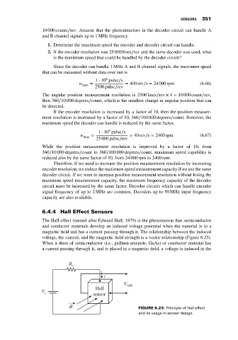
magnetic field and has a current passing through it. The relationship between the induced
voltage, the current, and the magnetic field strength is a vector relationship (Figure 6.23).
When a sheet of semiconductor (i.e., gallium-arsenide, GaAs) or conductor material has
a current passing through it, and is placed in a magnetic field, a voltage is induced in the
V out
Hall
sensor
B FIGURE 6.23: Principle of Hall effect
and its usage in sensor design.