
Page 362 - Mechatronics with Experiments
P. 362
JWST499-Cetinkunt
JWST499-c06
348 MECHATRONICS Printer: Yet to Come October 9, 2014 8:1 254mm×178mm
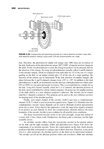
Photodetector
LED light source
Stationary mask
Rotating
encoder disk
FIGURE 6.20: Components and operating principle of a rotary absolute encoder: rotary disk
with absolute position coding in gray scale, LED set, phototransistor set, mask.
disk. Therefore, the photodetector output will change state 1000 times per revolution of
◦
◦
the disk. Each pulse of the photodetector means 360 ∕1000 of angular position change in
the shaft. If only one photodetector is used, the change in position can be detected, but not
the direction of the change. By using two photodetectors (usually called A and B channels
of the encoder output), which are displaced from each other by 1/2 of the size of a single
grading on the disk (or an integer number plus 1/2 of the size of a single grading), the
direction of the motion can be determined. If the disk direction of rotation changes, the
◦
◦
phase between the A and B channels changes from +90 to −90 . In addition to the dual
photodetectors A and B, an incremental encoder also has a third photodetector which turns
ON (or OFF) for one pulse period per revolution. This is accomplished by a single slit on
the disk. Using this channel (usually called the C or Z channel), the absolute position of
the disk can be established by a home motion sequence. On power-up, the angular position
of the shaft relative to a zero reference position is unknown. The encoder can be rotated
until the C channel is turned on. This position can be used as the zero reference position
for keeping track of the absolute position.
Finally, each output channel of the encoder (A,B,C) may have a complementary
̄
channel ( ̄ A, ̄ B, C) which is used as protection against noise. Figure 6.21 illustrates how the
complementary encoder output channels can be used to eliminate position measurement
errors due to noise. Notice that for this approach to work, the same noise signal is assumed
to be present on each channel. In short, the complementary channels improve the noise
immunity of the encoder, but this is not a solution for all possible noise conditions.
The linear incremental encoder works in the same principle, except that instead of
a rotary disk, it has a linear scale. Furthermore, the linear scale is stationary and the light
assembly moves.
An absolute encoder differs from the incremental encoder in the printed pattern
on the disk and the light assembly (LEDs and photodetectors). Figure 6.20 shows the
components of an absolute encoder. Notice the coded pattern on the disk. Each discrete
position of the disk corresponds to a unique state of photo detectors. Therefore, at any given
time (i.e., after power-up), the absolute position on the shaft can be determined uniquely.
The encoder can tell us the absolute position within one revolution. Multi turn absolute