
Page 382 - Mechatronics with Experiments
P. 382
JWST499-Cetinkunt
JWST499-c06
368 MECHATRONICS Printer: Yet to Come October 9, 2014 8:1 254mm×178mm
The magnitude of the sensor displacement, which is a sinusoidal function, is
A (w∕w ) 2
n
|x (t)| = (6.111)
ss
2 1∕2
2 2
{[1 − (w∕w ) ] + [2 (w∕w )] }
n
n
There are two different purposes for this type of sensor,
1. If the sensor is intended to be used to measure the acceleration of the base, then
we are interested in the ratio of the magnitude of the response to the magnitude of
excitation,
|x (t)| (1∕w ) 2
n
ss
| | = (6.112)
| 2 | 2 2 2 1∕2
| Aw | {[1 − (w∕w ) ] + [2 (w∕w )] }
n
n
2. If the sensor is intended to be used as a seismic instrument (i.e., for earthquake
measurements) and measure the displacement of the base, then we are interested in
the ratio of
(w∕w ) 2
|x (t)| n
ss
| | = (6.113)
2 2
2 1∕2
| | {[1 − (w∕w ) ] + [2 (w∕w )] }
| A | n n
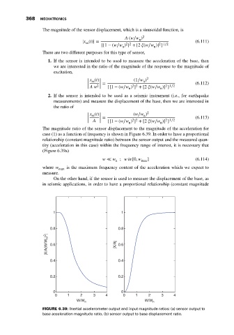
The magnitude ratio of the sensor displacement to the magnitude of the acceleration for
case (1) as a function of frequency is shown in Figure 6.39. In order to have a proportional
relationship (constant magnitude ratio) between the sensor output and the measured quan-
tity (acceleration in this case) within the frequency range of interest, it is necessary that
(Figure 6.39a)
w ≪ w ; win [0, w max ] (6.114)
n
where w max is the maximum frequency content of the acceleration which we expect to
measure.
On the other hand, if the sensor is used to measure the displacement of the base, as
in seismic applications, in order to have a proportional relationship (constant magnitude
1 1
0.8 0.8
|X/A(W/W n ) 2 | 0.6 |X/A| 0.6
0.4 0.4
0.2 0.2
0 0
0 1 2 3 4 0 1 2 3 4
W/W n W/W n
FIGURE 6.39: Inertial accelerometer output and input magnitude ratios: (a) sensor output to
base acceleration magnitude ratio, (b) sensor output to base displacement ratio.