
Page 386 - Mechatronics with Experiments
P. 386
JWST499-Cetinkunt
JWST499-c06
372 MECHATRONICS Printer: Yet to Come October 9, 2014 8:1 254mm×178mm
Active length: L = N *l
0
FIGURE 6.42: A typical strain gauge for strain measurement.
6.7 STRAIN, FORCE, AND TORQUE SENSORS
6.7.1 Strain Gauges
The most common strain measurement sensor is a strain gauge. The strain gauge transduc-
tion principle is based on the relationship between the change in length and its resulting
change in the resistance of a conductor. Typical strain-gauge material used is constantan
(55% copper and 45% nickel). A fine wire of strain-gauge material is given a directional
shape and bonded to the part surface using adhesive bonding materials. The resistance and
strain relationship is
ΔR ΔL
= G (6.127)
R 0 L 0
where G is called the gauge factor of the sensor, R is the nominal resistance, and L nominal
0
0
length under no strain conditions. In order to increase the resulting resistance change under
given strain conditions, we need to pack more length, L, into a sensor size. That is the
reason for the many rounds of conductor wire in one direction in the construction of a strain
gauge (Figures 6.42 and 6.43). Ideally, strain is the property at a point on a material and is
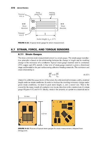
3.0 mm
4.0 mm 3
2
FIGURE 6.43: Pictures of typical strain gauges for strain measurement. Adapted from
Omega.com.