Page 388 - Mechatronics with Experiments
P. 388

JWST499-Cetinkunt
            JWST499-c06
                       374   MECHATRONICS  Printer: Yet to Come                       October 9, 2014 8:1  254mm×178mm


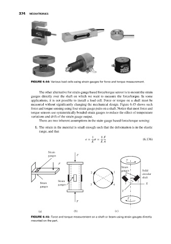
                              FIGURE 6.44: Various load cells using strain gauges for force and torque measurement.


                                   The other alternative for strain-gauge based force/torque sensor is to mount the strain
                              gauges directly over the shaft on which we want to measure the force/torque. In some
                              applications, it is not possible to install a load cell. Force or torque on a shaft must be
                              measured without significantly changing the mechanical design. Figure 6.45 shows such
                              force and torque sensing using four strain gauge pairs on a shaft. Notice that most force and
                              torque sensors use symmetrically bonded strain gauges to reduce the effect of temperature
                              variations and drift of the strain gauge output.
                                   There are two inherent assumptions in the stain-gauge based force/torque sensing:
                                1. The strain in the material is small enough such that the deformation is in the elastic
                                   range, and that
                                                                  1    1 F
                                                                 =     =                        (6.136)
                                                                  E    E A

                                        Strain
                                        gauges           F
                                                                                      T
                                              F
                                                                                   Strain
                                                                                   gauges      Solid
                                                                 2             1
                                                                                               circular
                                                                                         45°   shaft
                                              Strain                                         2
                                   Strain     gauges             3            4      1            X
                                   gauges
                                                                                   Y

                                                                                       T
                                                         F


                                  (a)                  (b)                     (c)
                              FIGURE 6.45: Force and torque measurement on a shaft or beam using strain gauges directly
                              mounted on the part.
   383   384   385   386   387   388   389   390   391   392   393