
Page 424 - Mechatronics with Experiments
P. 424
JWST499-Cetinkunt
JWST499-c07
410 MECHATRONICS Printer: Yet to Come October 9, 2014 8:41 254mm×178mm
(a) (b)
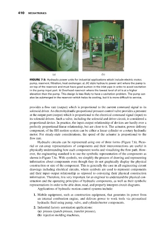
FIGURE 7.5: Hydraulic power units for industrial applications which include electric motor,
pump, reservoir, filtration, heat exchanger. a) JIC style hydraulic power unit where the pump is
on top of the reservoir and must have good suction in the inlet pipe in order to avoid cavitation
in the pump input port. b) Overhead reservoir where the lowest level of oil is at a higher
elevation than the pump. This design is less likely to have a cavitation problem. The pump can
also be submerged in the reservoir which helps its cooling, but it is more difficult to service.
provides a flow rate (output) which is proportional to the current command signal to its
solenoid driver. An electrohydraulic proportional pressure control valve provides a pressure
at the output port (output) which is proportional to the electrical command signal (input) to
its solenoid drivers. Such a valve, including the solenoid and driver circuit, is considered a
proportional device. In practice, the input–output relationship of devices are hardly ever a
perfectly proportional linear relationship, but are close to it. The actuator, power delivery
component, of the EH motion system can be either a linear cylinder or a rotary hydraulic
motor. For steady-state considerations, the speed of the actuator is proportional to the
flow rate.
Hydraulic circuits can be represented using one of three forms (Figure 7.6). Picto-
rial or cut-away representations of components and their interconnections are useful in
physically understanding how each component works and visualizing the flow path. How-
ever, the engineering standard is to use the symbolic representation of the components as
shown in Figure 7.6c. With symbols, we simplify the process of drawing and representing
information about components even though they do not graphically display the physical
construction or size of the component. This is generally the case in all engineering circuit
drawings including electrical circuits, where symbols are used to represent components
and their input–output relationship as opposed to conveying their physical construction
information. Therefore, it is very important for an engineer to understand the physical con-
struction and the operating principles of hydraulic components, as well as their symbolic
representations in order to be able draw, read, and properly interpret circuit diagrams.
Applications of hydraulic motion control systems include:
1. Mobile equipment, such as construction equipment, that generates its power from
an internal combustion engine, and delivers power to work tools via pressurized
hydraulic fluid using pump, valve, and cylinder/motor components.
2. Industrial factory automation applications:
(a) presses (punch presses, transfer presses),
(b) injection molding machines,