
Page 422 - Mechatronics with Experiments
P. 422
JWST499-Cetinkunt
JWST499-c07
408 MECHATRONICS Printer: Yet to Come October 9, 2014 8:41 254mm×178mm
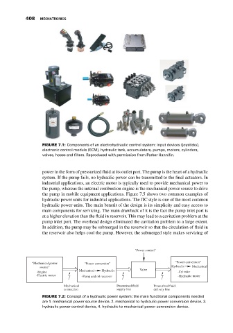
FIGURE 7.1: Components of an electrohydraulic control system: input devices (joysticks),
electronic control module (ECM), hydraulic tank, accumulators, pumps, motors, cylinders,
valves, hoses and filters. Reproduced with permission from Parker Hannifin.
power in the form of pressurized fluid at its outlet port. The pump is the heart of a hydraulic
system. If the pump fails, no hydraulic power can be transmitted to the final actuators. In
industrial applications, an electric motor is typically used to provide mechanical power to
the pump, whereas the internal combustion engine is the mechanical power source to drive
the pump in mobile equipment applications. Figure 7.5 shows two common examples of
hydraulic power units for industrial applications. The JIC style is one of the most common
hydraulic power units. The main benefit of the design is its simplicity and easy access to
main components for servicing. The main drawback of it is the fact the pump inlet port is
at a higher elevation than the fluid in reservoir. This may lead to a cavitation problem at the
pump inlet port. The overhead design eliminated the cavitation problem to a large extent.
In addition, the pump may be submerged in the reservoir so that the circulation of fluid in
the reservoir also helps cool the pump. However, the submerged style makes servicing of
"Power control"
“Mechanical power “Power conversion” “Power conversion”
source” Hydraulic Mechanical
Mechanical Hydraulic Valve
-Engine -Cylinder
-Electric motor -Pump and oil reservoir -Hydraulic motor
Mechanical Pressurized fluid Pressurized fluid
connection supply line delivery line
FIGURE 7.2: Concept of a hydraulic power system: the main functional components needed
are 1. mechanical power source device, 2. mechanical to hydraulic power conversion device, 3.
hydraulic power control device, 4. hydraulic to mechanical power conversion device.