
Page 418 - Mechatronics with Experiments
P. 418
JWST499-Cetinkunt
JWST499-c06
404 MECHATRONICS Printer: Yet to Come October 9, 2014 8:1 254mm×178mm
3. Consider a rotary motion axis and its speed control (i.e., speed control of a spindle of a CNC
machine tool or speed control of a precision conveyor). Assume that both high speed (w max =
3600 rpm) and low speed w min = 1 rpm speed control is required with 0.01 rpm regulation accuracy.
a) Determine specifications for a tachometer to meet the speed control requirements. b) Select an
optical incremental encoder and derive speed information from the position pulses digitally. What
is the speed estimation accuracy at minimum speed if the sampling period is 1.0 ms? Show how the
speed estimation can be improved with the time period measurement technique. What is the maximum
pulse frequency of the selected encoder at the maximum speed?
4. Consider the following measurement problems: i) seismic displacement measurement for earth-
quake monitoring, ii) three dimensional (horizontal, vertical, and lateral) acceleration of a car
body during travel, iii) and measurement of the same during an crash test. Discuss the expected
range of frequency content of the signals in each application and select appropriate sensors for the
measurement.
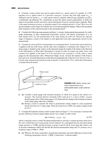
5. Consider the stress and force measurement on a rectangular beam. Assume that a horizontal force
is applied at the tip of the beam, and the other end is clamped to a stationary base (Figure 6.74). A
strain gauge is bonded on the surface at the mid point along the length of the beam in the direction
of the deformation. a) What other information is needed in order to measure the strain, stress, and
external force applied on the beam? b) If the maximum force expected is 1.0 kNt, select a strain
gauge for the measurement with a Wheatstone bridge circuit. Assume the material of the beam is
steel and cross-sectional dimensions (in the direction perpendicular to the force) are 10 cm × 5cm. c)
Can the same measurement system be used to measure a vertical force? If so, what other information
is needed about the beam?
Strain gauge
Force
FIGURE 6.74: Strain, stress, and
Cantilever beam
force measurement on a
deformable beam under external
load.
6. (a) Consider a strain gauge with nominal resistance of 120 Ω. It is glued on the surface of a
structure. The structure deforms nominally 0.001 strain level ( =Δl∕l = 0.001). Assume
that the gauge factor of the strain gauge is 2.0. Determine the change in the nominal resistance
of the strain gauge under this condition.
(b) Design a circuit to measure the strain as proportional voltage output to a data acquisition
board which has 0–5 V input range. When the strain level is 0.001, the output voltage should
be 5.0V.
7. Consider the hydraulic motion control system shown in Figure 7.3. It is necessary to measure the
pressure difference between pump output and the valve output. In other words,
Δp =max(p − p , p − p ) (6.197)
B
A
P
P
which is typically used to control the pump displacement to provide a constant pressure drop across
the valve (called the load sensing pump control method). It is anticipated that the maximum pump
output pressure is 15 MPa and the pressures at point A and B will be lower than that. Select a set
of pressure transducers which will provide the desired measurement range and 1% accuracy over a
frequency range of 0 Hz to 1 KHz.
8. (a) What are the basic temperature measurement principles and main differences between the
following temperature sensors: 1) RTD, 2) thermistor, 3) thermocouple?