
Page 414 - Mechatronics with Experiments
P. 414
JWST499-Cetinkunt
JWST499-c06
400 MECHATRONICS Printer: Yet to Come October 9, 2014 8:1 254mm×178mm
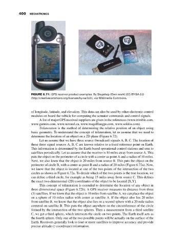
FIGURE 6.71: GPS receiver product examples. By Stepshep (Own work) [CC-BY-SA-3.0
(http://creativecommons.org/licenses/by-sa/3.0)], via Wikimedia Commons.
of longitude, latitude, and elevation. This data can also be used by other electronic control
modules on board the vehicle for computing the actuator commands and control signals.
A list of major GPS received suppliers are given in the references (www.trimble.com,
www.garmin.com, www.novatel.ca, www.magelllangps.com, www.sokkia.com).
Trilateration is the method of determining the relative position of an object using
basic geometry. To understand the concept of trilateration, let us assume that we need to
determine the location of an object on a 2D plane (Figure 6.72).
Let us assume that we have three source (broadcast) signals A, B, C. The location of
these three signal sources A, B, C are known relative to a fixed reference point on Earth.
This information is determined by the Earth based operational control stations and sent to
satellites periodically. Let us assume that the receiver is 10 miles away from source A. This
puts the object on the perimeter of a circle with a center as point A and a radius of 10 miles.
Next, we also know that the object is 20 miles from source B. This puts the object on the
perimeter of circle B, with a center as point B and a radius of 20 miles (Figure 6.72a). Now,
we know that the object is located at one of the two points of the intersection of the two
circles as shown in Figure 6.72a. To decide which of the two points is the true location, we
can define a third circle, for example as being 15 miles away from source C. This defines
the exact two-dimensional (2D) coordinates of the object to be located [X,Y].
This concept of trilateration is extended to determine the location of any object in
three-dimensional space (Figure 6.72b). A GPS receiver measures its distance from three
(3) satellites. If we know that the object is 10 miles from satellite A, we can place the object
on a sphere of 10 miles radius with center as satellite A. If the object also lies 20 miles
from satellite B, we know that the object also lies on a second sphere with a 20 mile radius
centered on satellite B. This puts the object anywhere on the circumference of the circle
formed by the intersection of the two spheres. Then a measurement from a third satellite
C, we get a third sphere, which intersects the circle on two points. The Earth itself acts as
the fourth sphere. Only one of the two possible points will be actually on the surface of the
Earth. Receivers generally look to four or more satellites to improve accuracy and provide
precise altitude (z-coordinate) information.