Page 428 - Mechatronics with Experiments
P. 428
JWST499-Cetinkunt
            JWST499-c07
                       414   MECHATRONICS  Printer: Yet to Come                      October 9, 2014 8:41 254mm×178mm
                                    Command input
                                    device                                                      Load
                                                  Controller
                                                                                            Cylinder
                                                                     Valve
                                                     Accumulator

                              Electric
                              motor/engine  Pump
                                                                P      B
                               M/E        P
                                                                              Cross-over
                                                                              relief valves
                                                                T      A
                                               Relief
                                               valve


                                                Filter                 Line relief
                                                                       valves
                                                Tank
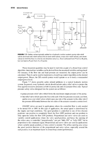
                              FIGURE 7.7: Safety valves typically added to a hydraulic motion system: pump side relief
                              valves and load side relief valves (line-to-tank relief valves, cross-over relief valves), and check
                              valves to limit the flow in a line to one direction only (i.e., flow is allowed from P to A or B ports,
                              but not back to P port from A or B ports).


                                   These measured quantities may be used in real-time as part of a closed loop control
                              algorithm. Intermediate variables can be derived from the measured variables and regulated.
                              For instance, if the flow rate and load pressure are measured, the output power can be
                              calculated. Then it can be used to implement a closed loop control algorithm on the desired
                              output power. Hence, the EH control system would operate so as to track a commanded
                              output power level.
                                   Figure 7.7 shows possible safety related additions to a typical hydraulic motion
                              system. In general, every hydraulic circuit should include safety relief valves to protect the
                              lines against excessive pressures at both (i) pump side and (ii) actuator (line) side. Typical
                              pressure safety valves designed into the system are as follows:

                                  pump pressure relief valve which limits the maximum output pressure of the pump,

                                  line relief valve which opens the line to the tank if the line pressure exceeds a set limit,

                                  and/or cross-over relief valves which open one side of the actuator to the other side if
                                  the pressure differential between the two sides of the actuator exceeds a certain level.

                                   ON/OFF valves are used in applications where the controlled flow is only needed
                              to be turned ON or OFF. In this type of application, the actual speed is determined by
                              the supply and load conditions. The spool position is controlled to one of two discrete
                              positions: one position to completely block the flow (OFF position) and one position to
                              fully open the orifice for flow (ON position). Proportional and servo valves are used on
                              variable control applications where the valve spool position, and hence the opening of
                              the orifice area, is controlled “proportionally,” not just “fully ON” or “fully OFF,” but in
                              proportion to the command signal. Proportional and servo valves are used in applications
                              where variable speed, position, or force control is needed. The orifice opening area versus
                              the spool position function of the proportional and servo valves, especially around the
                              null-position, is an important factor in closed loop control performance.

