Page 433 - Mechatronics with Experiments
P. 433
October 9, 2014 8:41 254mm×178mm
                                         Printer: Yet to Come
                        JWST499-Cetinkunt
            JWST499-c07
                                                            ELECTROHYDRAULIC MOTION CONTROL SYSTEMS  419
                                                                             Pressure line
                                                                             filter

                             Suction line
                             filter


                                                (a)                                 (b)


                                             Return line
                                             filter
                                                                      Case drain
                                                                       line filter
                                                (c)                                 (d)


                                         Kidney loop


                                                (e)
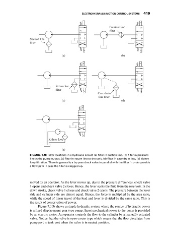
                             FIGURE 7.9: Filter locations in a hydraulic circuit: (a) filter in suction line, (b) filter in pressure
                             line at the pump output, (c) filter in return line to the tank, (d) filter in case drain line, (e) kidney
                             loop filtration. There is generally a by-pass check valve in parallel with the filter in order provide
                             a flow path in case the filter is clogged up.


                             moved by an operator. As the lever moves up, due to the pressure differences, check valve
                             1 opens and check valve 2 closes. Hence, the lever sucks the fluid from the reservoir. In the
                             down stroke, check valve 1 closes and check valve 2 opens. The pressure between the lever
                             side and cylinder side are almost equal. Hence, the force is multiplied by the area ratio,
                             while the speed of linear travel of the load and lever is divided by the same ratio. This is
                             the result of conservation of power.
                                  Figure 7.10b shows a simple hydraulic system where the source of hydraulic power
                             is a fixed displacement gear type pump. Input mechanical power to the pump is provided
                             by an electric motor. An operator controls the flow to the cylinder by a manually actuated
                             valve. Notice that the valve is open-center type which means that the flow circulates from
                             pump port to tank port when the valve is in neutral position.

