Page 437 - Mechatronics with Experiments
P. 437
October 9, 2014 8:41 254mm×178mm
                                         Printer: Yet to Come
            JWST499-c07
                        JWST499-Cetinkunt
                                                            ELECTROHYDRAULIC MOTION CONTROL SYSTEMS  423
                                    Command
                                   input devices
                                                               Controller
                                                                          DC P.S.
                                                                 DSP
                                                                        Amp   Amp


                                                              Open center            Open center
                                        Pump                  valve                  valve
                                                      P
                               M/E
                                                      T


                                        Reservoir
                                                                   Cylinder               Cylinder

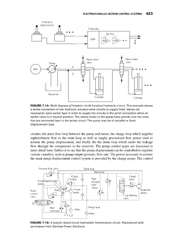
                             FIGURE 7.14: Multi degrees of freedom (multi function) hydraulic circuit. This example shows
                             a series connection of two hydraulic actuator-valve circuits to supply lines. Valves are
                             necessarily open-center type in order to supply the circuits in the serial connection when an
                             earlier valve is in neutral position. The valves closer to the pump have priority over the ones
                             that are connected later in the series circuit. The pump may be of variable or fixed
                             displacement type.

                             circuits: the main flow loop between the pump and motor, the charge loop which supplies
                             replenishment flow to the main loop as well as supply pressurized flow power used to
                             actuate the pump displacement, and finally the the drain loop which sends the leakage
                             flow through the components to the reservoir. The pump control types are discussed in
                             more detail later. Suffice it to say that the pump displacement can be controlled to regulate
                             various variables, such as pump output pressure, flow rate. The power necessary to actuate
                             the main pump displacement control system is provided by the charge pump. The control


                                  Pressure limit valve       Drain loop
                                                                   Main loop
                                                     Charge                            Charge
                                                     relief      High                  relief
                                  Pump displacement              pressure
                                  piston
                                                                 relief
                                                                 valves
                             Pump           Pump       Charge                                 Hydraulic
                                                       pump
                             control                                                          motor
                                                                                    Loop flushing
                             valve
                                                                                    valve
                                         Heat                  Charge loop
                                                       Filter
                                         exchanger
                                                                Filter
                             FIGURE 7.15: A typical closed circuit hydrostatic transmission circuit. Reproduced with
                             permission from Danfoss Power Solutions.

