
Page 439 - Mechatronics with Experiments
P. 439
JWST499-Cetinkunt
Printer: Yet to Come
JWST499-c07
October 9, 2014 8:41 254mm×178mm
ELECTROHYDRAULIC MOTION CONTROL SYSTEMS 425
3. mechanical plus pilot hydraulics actuated valve,
4. electrical plus pilot hydraulics actuated valve.
The focus in the classification is the source of actuation power for shifting the valve spool.
In mechanically controlled valves, the operator pushes a lever which is connected to the
main spool via a mechanical linkage. This is used in relatively small size mobile equipment
applications. The same concept is extended to large size machine applications by using an
intermediate pilot pressure circuit to actuate the main valve. The motion of the pilot valve
is still controlled by direct mechanical motion of the lever. The pilot valve is essentially a
proportional pressure reducing valve. It has a constant pilot pressure supply port and a tank
port. The output pilot pressure is proportional to the lever displacement at a value between
the tank port pressure and pilot supply port pressure. The main valve spool is shifted in
proportion to the output pilot pressure.
Finally, if the spool displacement power comes from the electromagnetic force which
is generated by an electric current in the solenoid winding, then it is an electrically controlled
valve. Such hydraulic systems are called electrohydraulic (EH) systems. The EH valves
may be single stage for small power applications or multi stage for large power applications.
In multi stage EH valves, the electrical current in the solenoid moves the first stage valve
spool (pilot spool), and then the motion of the pilot spool is amplified via a pilot output
pressure line to move the main valve spool. In short, pilot-actuated multi stage valves may be
controlled by the mechanical connection to the control lever (mechanically controlled multi
stage hydraulic valve (Figure 7.16b)) or by an electrical actuator (electrically controlled
(EH) multi stage valve, Figure 7.16d).
7.2 FUNDAMENTAL PHYSICAL PRINCIPLES
In this section we briefly review the fundamental principles of physics that govern hydraulic
circuits. Namely, we discuss the Pascal’s law and Bernoulli’s equation.
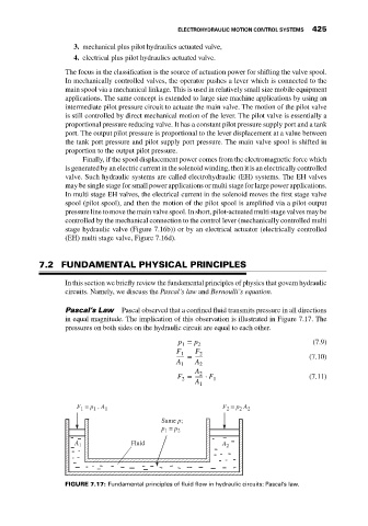
Pascal’s Law Pascal observed that a confined fluid transmits pressure in all directions
in equal magnitude. The implication of this observation is illustrated in Figure 7.17. The
pressures on both sides on the hydraulic circuit are equal to each other.
p = p (7.9)
1 2
F 1 F 2
= (7.10)
A A
1 2
A 2
F = ⋅ F (7.11)
2 1
A
1
F = p . A 1 F = p A 2
1
2
2
1
Same p;
p = p 2
1
A 1 Fluid A 2
FIGURE 7.17: Fundamental principles of fluid flow in hydraulic circuits: Pascal’s law.