Page 438 - Mechatronics with Experiments
P. 438

JWST499-Cetinkunt
            JWST499-c07
                       424   MECHATRONICS  Printer: Yet to Come                      October 9, 2014 8:41 254mm×178mm
                              of pump displacement is performed by the control valve which is actuated based on the
                              control objective. In closed circuit hydraulic circuits, ideally there is no leakage nor need
                              for replenishment fluid. In reality, it is desirable to have a certain amount of leakage. It is
                              through the leakage and the replenishment circuits that fluid under high pressure is removed
                              from the main loop, cooled by the heat exhanger, cleaned by filters and reinjected back
                              into the main loop. Therefore, the leakage and charge pump relenishment is an essential
                              part of all practical closed circuit hydraulic systems. In fact, the leakage rate is planned
                              into the circuit design and regulated at a planned rate by a so called loop flushing valve.
                              A typical system also includes various pressure relief valves between different sides of
                              hydraulic lines.
                                   The pump is a variable displacement type bidirectional pump. By changing the direc-
                              tion of fluid flow, the direction of speed of the hydraulic motor is changed. By controlling
                              the pump, the flow rate and hence the speed of the hydraulic motor, is controlled. Similarly,
                              if the pump is controlled to maintain a certain pressure, the torque output at the hydraulic
                              motor is controlled.
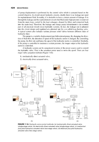
                                   A hydraulic system can be categorized in terms of the power source used to control
                              the hydraulic valve. That is the actuation power used to move the spool. There are four
                              major valve actuation methods (Figure 7.16):

                                1. mechanically direct actuated valve,
                                2. electrically direct actuated valve,


                                         Control lever                        Control lever
                                                                                Pilot valve

                           Engine                                   Pilot pump


                                                                    Engine
                                Pump
                                            Valve
                                                                   Main pump
                                                   Actuator                        Main valve
                                   Reservoir                                                Actuator
                                                                         Reservoir
                                           (a)                                  (c)

                                                                                    P.S. / battery
                                               P.S. / battery
                                                                           Sensor  ECU  Amp
                                                                    Control lever
                                     Sensor  ECU  Amp
                                                                                        Pilot valve
                              Control lever
                                                                            Pilot pump
                                   Engine
                                                                             Engine
                                     Pump      Main valve
                                                       Actuator
                                        Reservoir                          Main pump
                                                                                         Main valve  Actuator
                                                                                 Reservoir
                                           (b)                                           (d)
                              FIGURE 7.16: Hydraulic valve control methods: (a) mechanically direct actuated valve
                              (single-stage valve), (b) electrically direct actuated valve (single-stage valve), (c) mechanical
                              plus pilot hydraulics actuated valve (two-stage valve), (d) electrical plus pilot hydraulics
                              actuated valve (two-stage valve).
   433   434   435   436   437   438   439   440   441   442   443