Page 436 - Mechatronics with Experiments
P. 436
JWST499-Cetinkunt
            JWST499-c07
                       422   MECHATRONICS  Printer: Yet to Come                      October 9, 2014 8:41 254mm×178mm
                                    Command
                                   input devices
                                                              Controller
                                                                        DC P.S.
                                                               DSP
                                                                      Amp   Amp


                                        Pump
                                                      P
                               M/E
                                                      T


                                        Reservoir
                                                       Valve
                                                                 Cylinder

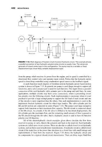
                              FIGURE 7.13: Multi degrees of freedom (multi function) hydraulic circuit. This example shows
                              a parallel connection of two hydraulic actuator-valve circuits to supply lines. The valves are
                              generally of closed center type in this configuration. The pump may be a variable or fixed
                              displacement type (most likely variable displacement type).


                              from the pump, which receives its power from the engine, and its speed is controlled by a
                              directional flow control valve and operator input switch. Notice that the hydraulic motor
                              speed is closed loop controlled using a tachometer speed sensor as the feedback signal.
                                   A multi function (multi degrees of freedom motion) hydraulic power based motion
                              system is shown in Figure 7.13. In general one pump is used (large enough to support all
                              functions), and a valve-actuator pair is used for each function. This figure shows a parallel
                              connection of the each hydraulic valve-actuator pair to the pump and tank lines. In some
                              applications, multiple circuits may have series connections, where a preceeding circuit
                              has priority over the following circuits. Such implementation is necessary when it is not
                              practical to provide a large enough pump to support the full load of each circuit and one
                              of the circuits is more important than the others. One such implementation is used in the
                              implement (bucket) hydraulic circuit for wheel type loaders. The valve-cylinder pair for
                              lift and tilt motion are connected in series (Figure 7.14). The pump is not large enough to
                              support both functions at their maximum flow capacity. The tilt circuit is connected ahead
                              of the lift circuit. As a result, if the tilt valve is shifted to its maximum displacement, the
                              tilt cylinder gets the maximum flow, and the remaining small amount of flow is passed to
                              the lift circuit through the tilt valve. Such a hydraulic circuit is said to have tilt function
                              priority over lift function.
                                   All of the electrohydraulic circuit examples given above circulate the flow from
                              reservoir to pump, to valve, then to the actuators and back to the reservoir. Such hydraulic
                              systems are called open circuit systems. There are also the so called closed circuit hydraulic
                              systems, such as those used in hydrostatic transmissions. A hydraulic circuit is called closed
                              circuit if the main flow in the power line circulates in a closed line with small leakage and
                              replenishment of fluid from the reservoir. Figure 7.15 shows the hydraulic circuit and
                              its components for a typical closed circuit transmission. There are three major fluid flow

