Page 432 - Mechatronics with Experiments
P. 432
JWST499-Cetinkunt
            JWST499-c07
                       418   MECHATRONICS  Printer: Yet to Come                      October 9, 2014 8:41 254mm×178mm
                              of actuator-sensor non-colocation and the resulting transport delay (pure time delay) in a
                              control system.

                              Example    Consider a hydraulic motion system where an accumulator is to be selected.
                              Let the maximum and minimum line pressures be 3000 psi and 90% of that (2700 psi),
                              respectively. Let n = 1.4 nominally for the nitrogen gas. Let the discharge volume to be
                              1 gallon. Calculate the necessary accumulator volume.
                                   Let the precharge pressure to be 90% of the minimum pressure. Hence
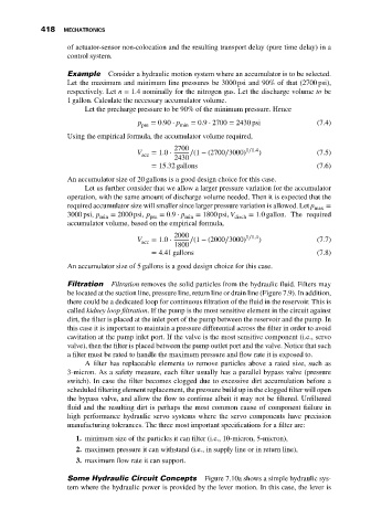
                                                 p pre  = 0.90 ⋅ p min  = 0.9 ⋅ 2700 = 2430 psi   (7.4)
                              Using the empirical formula, the accumulator volume required,
                                                           2700               1∕1.4
                                                 V   = 1.0 ⋅   ∕(1 − (2700∕3000)  )               (7.5)
                                                  acc
                                                           2430
                                                     = 15.32 gallons                              (7.6)
                              An accumulator size of 20 gallons is a good design choice for this case.
                                   Let us further consider that we allow a larger pressure variation for the accumulator
                              operation, with the same amount of discharge volume needed. Then it is expected that the
                              required accumulator size will smaller since larger pressure variation is allowed. Let p max  =
                              3000 psi, p  = 2000 psi, p  = 0.9 ⋅ p  = 1800 psi, V  = 1.0 gallon. The required
                                       min          pre       min          disch
                              accumulator volume, based on the empirical formula,
                                                           2000               1∕1.4
                                                 V   = 1.0 ⋅   ∕(1 − (2000∕3000)  )               (7.7)
                                                  acc
                                                           1800
                                                     = 4.41 gallons                               (7.8)
                              An accumulator size of 5 gallons is a good design choice for this case.

                              Filtration  Filtration removes the solid particles from the hydraulic fluid. Filters may
                              be located at the suction line, pressure line, return line or drain line (Figure 7.9). In addition,
                              there could be a dedicated loop for continuous filtration of the fluid in the reservoir. This is
                              called kidney loop filtration. If the pump is the most sensitive element in the circuit against
                              dirt, the filter is placed at the inlet port of the pump between the reservoir and the pump. In
                              this case it is important to maintain a pressure differential across the filter in order to avoid
                              cavitation at the pump inlet port. If the valve is the most sensitive component (i.e., servo
                              valve), then the filter is placed between the pump outlet port and the valve. Notice that such
                              a filter must be rated to handle the maximum pressure and flow rate it is exposed to.
                                   A filter has replaceable elements to remove particles above a rated size, such as
                              3-micron. As a safety measure, each filter usually has a parallel bypass valve (pressure
                              switch). In case the filter becomes clogged due to excessive dirt accumulation before a
                              scheduled filtering element replacement, the pressure build up in the clogged filter will open
                              the bypass valve, and allow the flow to continue albeit it may not be filtered. Unfiltered
                              fluid and the resulting dirt is perhaps the most common cause of component failure in
                              high performance hydraulic servo systems where the servo components have precision
                              manufacturing tolerances. The three most important specifications for a filter are:

                                1. minimum size of the particles it can filter (i.e., 10-micron, 5-micron),
                                2. maximum pressure it can withstand (i.e., in supply line or in return line),
                                3. maximum flow rate it can support.

                              Some Hydraulic Circuit Concepts      Figure 7.10a shows a simple hydraulic sys-
                              tem where the hydraulic power is provided by the lever motion. In this case, the lever is

